

Method and fluid for controlling saturation of formation around well
A well fluid and rock formation technology, applied in the field of drilling, which requires liquid circulation, can solve the problem of not being able to provide high lubricating performance
- Summary
- Abstract
- Description
- Claims
- Application Information
AI Technical Summary
Problems solved by technology
Method used
Image


Examples
Embodiment 1
[0095] The experiment was the injection of brine with or without the additive according to the invention into a presaturated porous medium in the presence of oil and water under Swi (initial water saturation) conditions (type (i) test).
[0096] The results are given in the table below:
[0097] Sw(%)
[0098] -Sw is the water saturation (percentage of water contained in the pore volume)
[0099] -Ko is the permeability of the rock core sample to oil expressed in millidarcy (expressed in SI unit, the conversion factor is: 1 Darcy=9.87×10 -13 m 2 ).
[0100] In the presence of 0.1 g / l PG8 / 10 additive in brine the result becomes:
[0101] Sw(%)
[0102]These leaching tests show that the addition of 0.1 g / l of PG8 / 10 additive can remove most of the residual water. Addition of additives to the brine injected into the porous media can thus alter the saturation by displacing residual water, thus resulting in higher oil saturation. It should be noted that...
Embodiment 2
[0103] The same experiment was carried out in the presence of 0.5 g / l polymer (polyacrylamide PAM) to approximate the actual composition of water-based mud filtrate. In the presence of PAM alone, there was no change in residual water saturation. However, the oil permeability decreases due to the adsorption of the polymer on the rock and due to the clogging of its pores by the polymer particles. As can be seen from the examples below, when PG8 / 10 was added, most of the residual water was displaced. It should also be noted that the reduction in oil permeability of the rock is less than in the presence of PAM alone.
[0104] Sw(%)
[0105] In the presence of 0.1 g / l PG8 / 10 in brine the result becomes:
[0106] Sw(%)
[0107] It can be concluded that the addition of PG8 / 10 removed most of the residual water and limited the decrease in oil permeability even in the presence of polymer.
Embodiment 3
[0108] Example 3: Variation in Saturation (Complete Formulation)
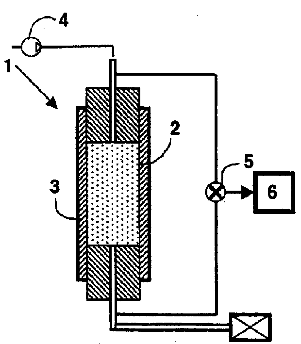
[0109] To get closer to actual conditions, dynamic filtering is performed and then the re-establishment of well production is simulated (type (ii) test). A water-based mud formulation is called FLOPRO, which is sold by MI Drilling Fluids Company (USA).
[0110] Its composition is as follows:
[0111] FLOVIS®: 6 g / l (xanthan gum - tackifier)
[0112] FLOTROL®: 7g / l (starch-water loss reducer)
[0113] HY-MOD PRIMA®: 28.5 g / l (filler clay)
[0114] NaCl: 20g / l
[0115] KCl: 20g / l
[0116] IDCARB 75®: 360g / l (carbonate)
[0117] pH=8
[0118] The result is as follows:
[0119] Sw(%)
[0120] In the presence of 0.1 g / l PG8 / 10 in brine the result becomes:
[0121] Sw(%)
[0122] These experiments carried out on the complete formulation confirmed that good results were obtained with respect to saturation (29% saturation of residual water after oil refluxing in the presence of 1 g / l ...
PUM
| Property | Measurement | Unit |
|---|---|---|
| Density | aaaaa | aaaaa |
| Viscosity | aaaaa | aaaaa |
Abstract
Description
Claims
Application Information