Antifriction bearing apparatus

A technology for rolling bearings and launching devices, which is applied in the direction of rolling contact bearings, roller bearings, bearing assembly, etc. It can solve problems such as troublesome assembly, high precision, and breakage, and achieve the effects of preventing cost increases, improving detection accuracy, and simplifying manufacturing

Inactive Publication Date: 2003-11-12
NSK LTD
View PDF4 Cites 11 Cited by
  • Summary
  • Abstract
  • Description
  • Claims
  • Application Information

AI Technical Summary

Problems solved by technology

If the supports 7, 7 are rotated relative to the housing 3, there is a risk that the wires 13, 13 will break
[0010] (2) Since each support 7, 7 has a plurality of protrusions 9, 9 screwed onto the main body 8, it is cumbersome to assemble
With this arrangement, it is difficult to detect the load applied axially to the rolling bearing with high accuracy

Method used


Image

  • Antifriction bearing apparatus
  • Antifriction bearing apparatus
  • Antifriction bearing apparatus

Examples


Embodiment Construction

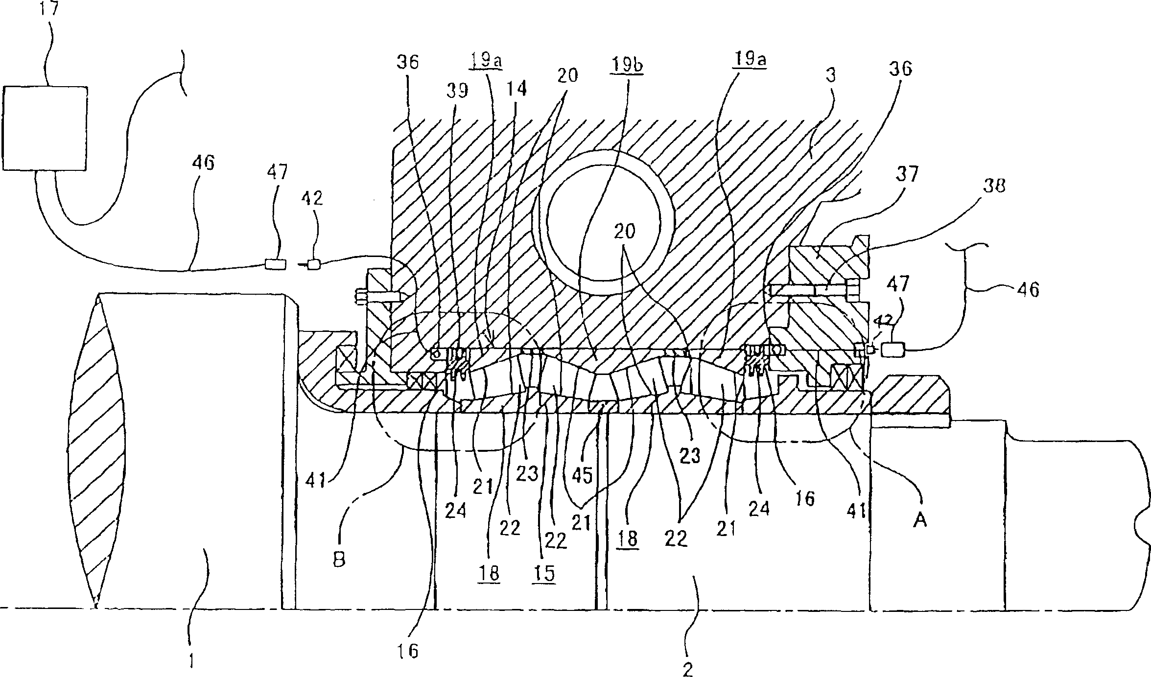
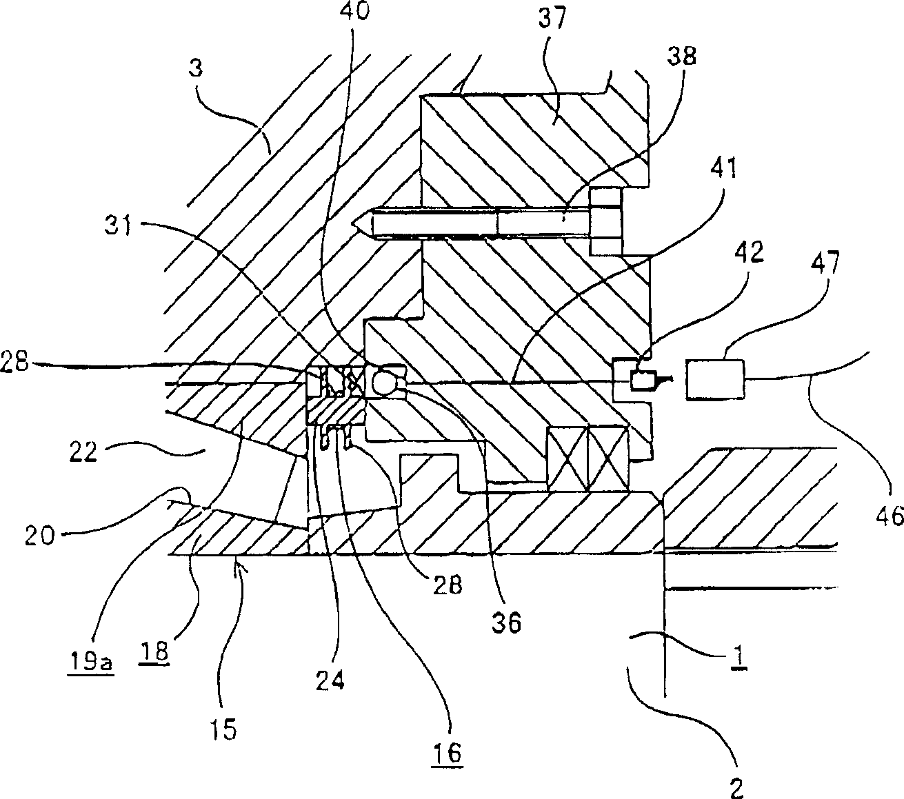
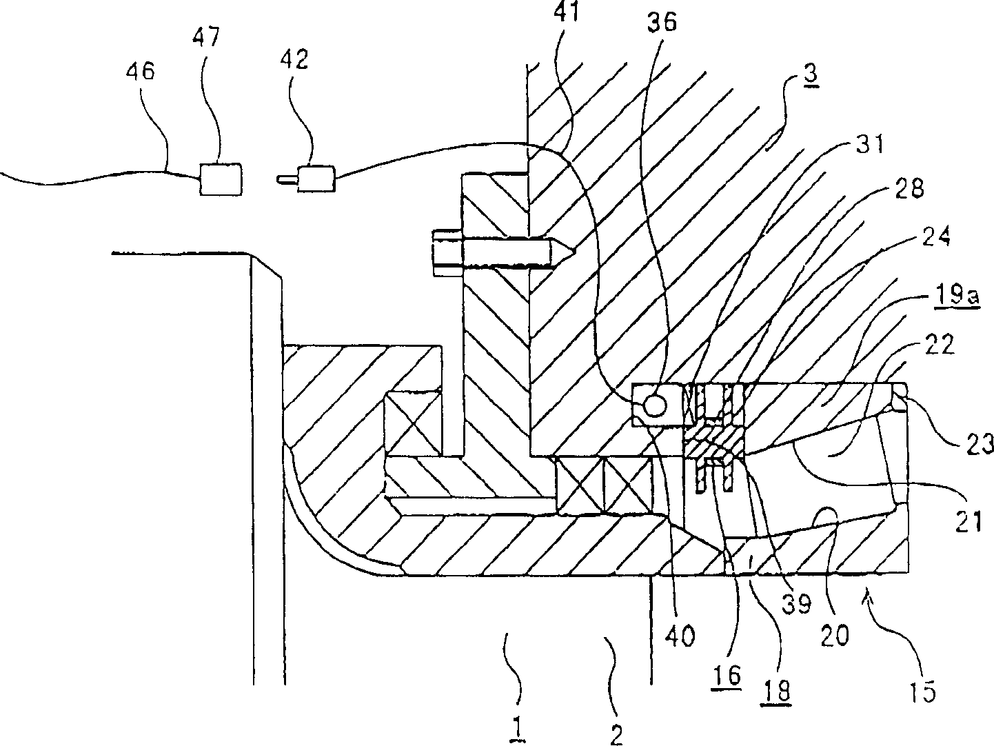
[0040] Figures 1 to 7 Each of the figures in FIG. 1 shows a rolling bearing device with a sensor device according to a first embodiment of the present invention. In the first embodiment, the two axial ends of the roll 1 rolling in the rolling mill, the rolling bearing device 14 with the sensor is connected in the rotating support part, so as to roll metal material such as steel. In detail, the roll neck 2 is disposed at the central portion on both axial ends of the rolling roll 1, and is rotatably supported within the housing 3 by four-row tapered roller bearings 15 even during use. The housing does not rotate either. The rolling bearing device 14 includes: a four-row tapered roller bearing 15, a pair of sensor devices 16, 16, a pair of second coils 36, 36, and an external input / output device 17 (Fig. 6). The four-row tapered roller bearing 15 includes: a pair of inner rings 18, 18, three outer rings 19a, 19b, raised conical inner ring raceways 20, 20, concave conical outer...


PUM


Abstract

A four-row tapered roller bearing is incorporated in the clearance between the inner surface of a housing and the outer surface of a rolling roller. A pair of supporting members supporting sensor devices are fitted in and supported by a part of the inner surface of the housing in such a manner that they are opposed to the ends of outer rings of the four-row tapered roller bearing disposed close to the both axial ends thereof. The sensor devices each comprise a distortion gauge as a detecting portion and a first coil for transmitting as a wireless signal a signal obtained by processing an output signal outputted from the distortion gauge. A second coil for receiving the wireless signal transmitted by the first coil is retained on a part of a member other than the supporting members.

Description

technical field [0001] The present invention relates to a rolling bearing device comprising a rolling bearing and a sensor device which rollably supports various rolls of iron and steel rolling mills, paper machines, etc. Axial load), so as to judge the degree of damage of the machine, or adjust the axial load to prolong the life of the bearing. Background technique [0002] For example, in work, the rolling bearings that support the roll necks of the rolls of iron and steel rolling mills bear not only radial loads, but also axial and axial loads. This axial load varies with the degree of deformation of the rolling mill. Therefore, the damage degree of the rolling mill can be judged by detecting the axial load. Further, based on the axial load thus measured, the fatigue life of the rolling bearing can be extended by adjusting the axial load applied to the components constituting the outer ring or the inner ring of the rolling bearing to an appropriate value. . [0003] ...

Claims


Application Information

Patent Timeline
Patent Type & Authority Applications(China)
IPC IPC(8): G01L5/12B21B31/07B21B33/00B21B38/00F16C19/38F16C19/52F16C35/07F16C41/00G01L5/00G08C17/02G08C19/38
CPCF16C19/522B21B38/00B21B33/00F16C13/02B21B31/07G08C19/38F16C19/388F16C41/008B21B2203/38B21B2038/002F16C2322/12
Inventor 佐藤幸夫今野胜广
Owner NSK LTD
Why Eureka
Try Eureka