
Interconnected optical fibre network systems

An optical fiber network, fully interconnected technology, applied in the field of optical communication systems or equipment, can solve problems such as unbearable and expensive

Inactive Publication Date: 2003-11-19
HUAZHONG UNIV OF SCI & TECH
View PDF0 Cites 8 Cited by
  • Summary
  • Abstract
  • Description
  • Claims
  • Application Information

AI Technical Summary

Problems solved by technology

If the transmission rate of the system is 10Gbps or higher, the price of this wavelength division multiplexing fully interconnected optical fiber transmission network system is very expensive and unaffordable

Method used


Image

  • Interconnected optical fibre network systems
  • Interconnected optical fibre network systems
  • Interconnected optical fibre network systems

Examples


Embodiment Construction

[0017] The present invention will be described in detail below in conjunction with the accompanying drawings.

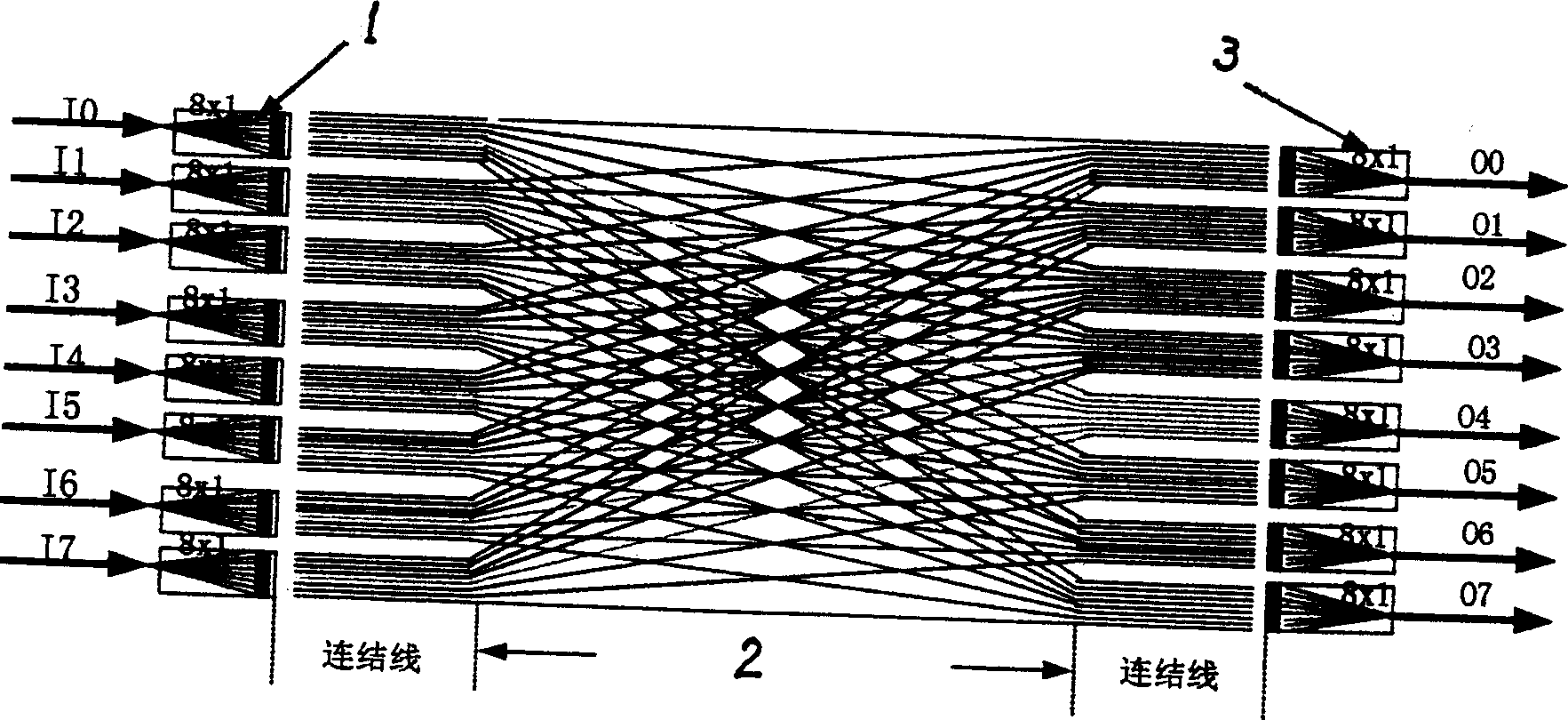
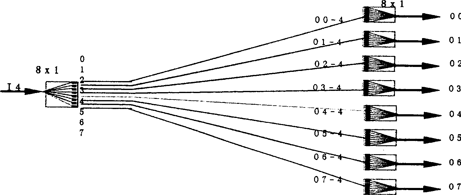
[0018] A) figure 2 As shown, the 8×8 fully interconnected optical fiber network system is taken as an example to illustrate, where M=8, N=1, the system consists of routing and gating transmission module 1 with 8×1 switches, 8×8 fully interconnected optical fibers It consists of a network component 2 and a receiving module 3 with an 8×1 switch routing gate. The input port of the system is marked as I 0 , I 1 , I 2 , I 3 , I 4 , I 5 , I 6 , I 7 , the flag of the output port is O 0 , O 1 , O 2 , O 3 , O 4 , O 5 , O 6 , O 7 , each input port has 8 channels to each output port as a dedicated data information transmission channel, the first 0 The 8 data transmission channels of the input port are respectively connected with the mark as O 0 , O 1 , O 2 , O 3 , O 4 , O 5 , O 6 , O 7 The 0th channel of the output port is connected, the Ith 1 The 8 d...


PUM


Abstract

The present invention includes route gated transmitting / receiving module and MXM all interconnected optical fibre network component. There are M number of route gated transmitting modules as each of them is equipped with surface-emitting laser array chip and circuit gate switch chip as well as there M number of route gated receiving modules as each of them is equipped with parallel array detector chip and switch chip. The MXM all interconnected optical fibre network component comprises M number of optical cables as each of them has MXN number of fibre core with optical cable head end connected to rout gated transmitting module and tail end connected to rout gated receiving module in sequence separately. It makes data channel an increase of dozens of times.

Description

technical field [0001] The invention belongs to an optical communication system or equipment and can be used in the fields of computer and communication. Background technique [0002] Information technology is developing in the direction of broadband, high speed, and large capacity. The capacity required for router equipment in communication technology is increasing, from 10Gbit, 100Gbit to Tbit level. The computing speed required in the field of parallel processing computers is getting higher and higher. Its architecture can be a high-performance parallel processing system composed of a large number of micro-processing chips interconnected by an interconnection switching network, and a cluster system composed of a large number of stand-alone motherboards interconnected. Many clusters are interconnected to form a grid computing system. In the traditional electronic interconnection switching network system technology, a large number of matrix switches such as 4×4, 8×8, 16×16,...

Claims


Application Information

Patent Timeline
Patent Type & Authority Applications(China)
IPC IPC(8): G02B6/26G02B6/28G02B6/42H04B10/25H04J14/02
Inventor 曹明翠罗风光罗志祥周新军
Owner HUAZHONG UNIV OF SCI & TECH
Learn More