Cathod-ray tube
A cathode ray tube and coil technology, which is applied in the direction of cathode ray tube/electron beam tube, discharge tube, electrode device and related components, etc., can solve the problems such as the deterioration of the heating performance of the deflection yoke, the reduction of the leakage magnetic field, and the difficulty in
- Summary
- Abstract
- Description
- Claims
- Application Information
AI Technical Summary
Problems solved by technology
Method used
Image
Examples
Embodiment 1
[0055] Figure 6 is a schematic structural view showing a deflection yoke according to the invention. Such as Figure 6 As shown, the deflection yoke comprises a horizontal deflection coil 51 on the screen side, and a ferrite core 57 between the screen side (s) and the neck side (n). Here, the base 55 is installed between the horizontal deflection coil 51 and the ferrite core 57 for insulating them, and the vertical deflection coil 53 is installed between the base 55 and the ferrite core 57 . Therefore, the sequence of element arrangement inside the deflection yoke is the horizontal deflection coil 51, the base 55, the vertical deflection coil 53 and the ferrite core 57. The deflection yoke is preferable to reduce the diameter of the end of the ferrite core near the screen side and to reduce the length of the ferrite core in the tube axis direction.
[0056] When the ferrite core 57 is fixed on the outer surface of the seat 55, the installation position of the end of the neck...
Embodiment 2
[0078] In the present invention ( Figure 10A ) and prior art ( Figure 10B ) shows the positional relationship between the ferrite core and the horizontal deflection coil in the deflection yoke where TPS has been adopted. deflection yoke using TPS with Figure 7A and Figure 7B The deflection yoke has the same concept and principle.
[0079] According to the scanning method used in ordinary CRTs, if viewed from a screen, electron beams from an electron gun scan from left to right to configure the screen. However, according to the scanning method used for the TPS type CRT, if viewed from the screen, electron beams emitted from the electron gun scan from top to bottom or bottom to top to configure the screen. In short, the scanning method used in the TPS type CRT is different from the conventional scanning method in that it scans by an electron beam rotated by 90 degrees. Therefore, compared with the electron beam array of the electron gun of common CRT, the electron beam ...
Embodiment 3
[0083] Example 3 to explain. [Example 3]
[0084] Embodiment 3 The deflection yoke with a high deflection angle greater than 110° and Figure 7A and Figure 7B The deflection yoke has the same principle.
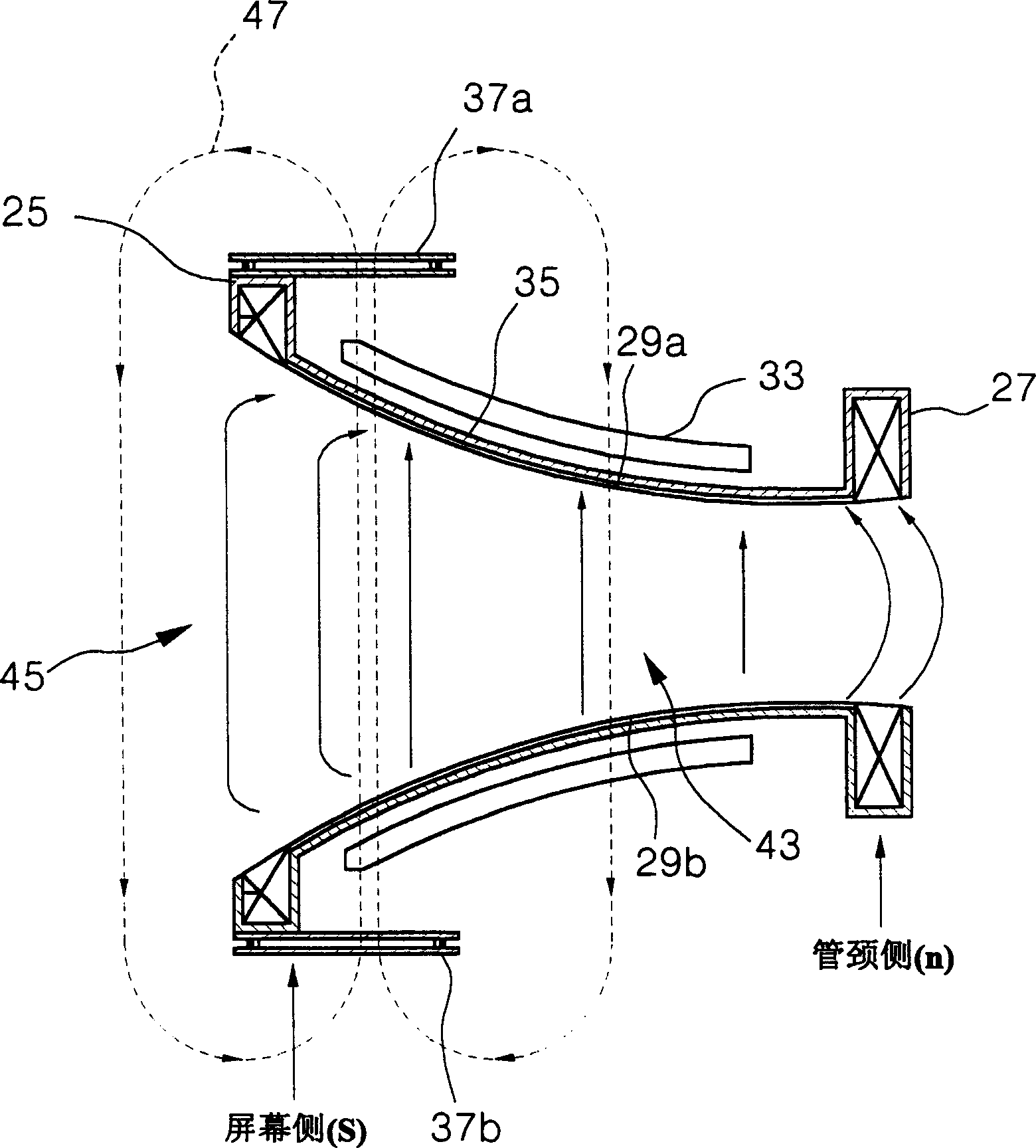
[0085] Such as Figure 7A and Figure 7B As shown, that is to say, in the deflection yoke with high deflection angle greater than 110°, the interval between the end of the horizontal deflection coil near the screen side and the end of the ferrite core near the screen side is the horizontal deflection coil in the tube 27% to 50% of the length Lh in the axial direction.
[0086] Furthermore, in the deflection yoke with a high deflection angle of more than 110°, the diameter Rc of the end of the ferrite core near the screen side is 50% to 85% of the diameter of the end of the horizontal deflection coil near the screen side.
[0087] The leakage magnetic field was measured by using the range of conditions shown in Table 1, which was lower than 20 nT.
[0088] pro...
PUM
 Abstract
Description
Claims
Application Information
 - R&D
- Intellectual Property
- Life Sciences
- Materials
- Tech Scout
- Unparalleled Data Quality
- Higher Quality Content
- 60% Fewer Hallucinations
Browse by: Latest US Patents, China's latest patents, Technical Efficacy Thesaurus, Application Domain, Technology Topic, Popular Technical Reports.
© 2025 PatSnap. All rights reserved.Legal|Privacy policy|Modern Slavery Act Transparency Statement|Sitemap|About US| Contact US: help@patsnap.com


