Phase modulator and phase modulating method
A phase modulation and phase modulator technology, which is applied in safety communication devices, phase modulation carrier systems, transmission systems, etc., can solve problems such as high-speed obstacles and inability to function normally.
- Summary
- Abstract
- Description
- Claims
- Application Information
AI Technical Summary
Problems solved by technology
Method used
Image

Examples
Embodiment 1
[0056] In Embodiment 1, a high-speed modulation method of phase modulation quantum cryptography is described, which is characterized in that, in the use of phase modulation quantum cryptography, a plurality of phase modulators are arranged in parallel and switched at high speed by an optical switch.
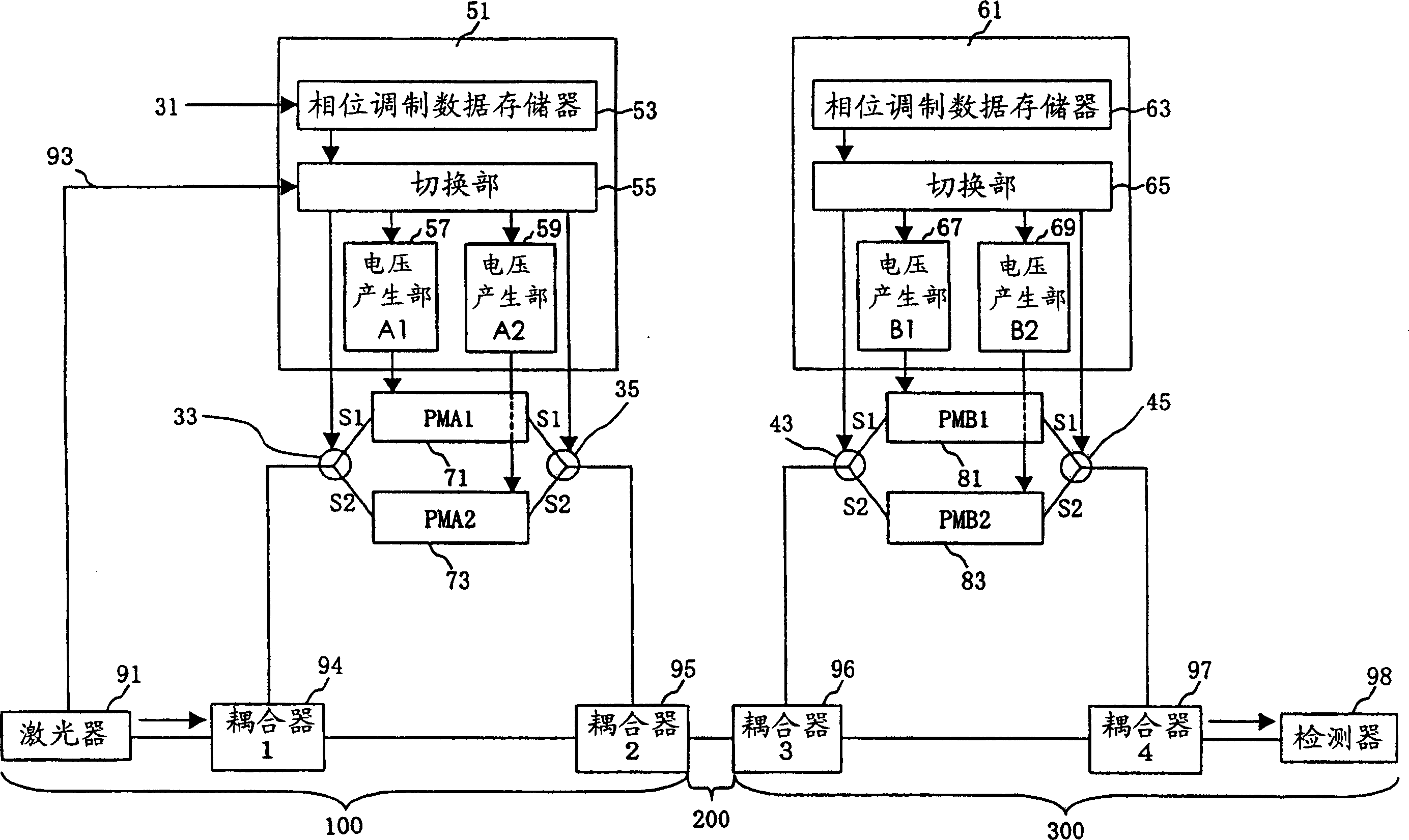
[0057] figure 1 A high-speed modulation system of quantum cryptography representing a phase modulation method.
[0058]This modulation system is composed of a transmission device 100 , a transmission path 200 and a reception device 300 . In the transmission device 100, the laser 91 oscillates the optical signal at the repetition frequency C to continuously generate the optical signal. The first coupler 94 and the second coupler 95 separate and combine optical signals. The first phase modulator 71 and the second phase modulator 73 perform phase modulation on the optical signal. The first optical switch 33 and the second optical switch 35 switch the first phase modulator 71 and...
Embodiment 2
[0070] Figure 4 is a diagram showing another example of the transmitting device 100 (or the receiving device 300).
[0071] exist Figure 4 , indicating that the four phase modulators of the first phase modulator 71, the second phase modulator 73, the third phase modulator 75, and the fourth phase modulator 77 are connected in parallel to use the first optical switch 33 and the second optical switch 35 Switching situation. The voltage generator 58 always generates 0V, 4V, 8V, and 12V in order to perform phase modulation of four quantities of 0, π / 2, π, and 3π / 2. 0V is supplied to the first phase modulator 71 . 4V is supplied to the second phase modulator 73 . 8V is supplied to the third phase modulator 75 . 12V is supplied to the fourth phase modulator 77 .
[0072] Figure 5 It is an operation explanatory diagram of the first phase modulator 71 , the second phase modulator 73 , the third phase modulator 75 , and the fourth phase modulator 77 . The first phase modulator ...
Embodiment 3
[0078] In the present embodiment 3, a high-speed modulation method of quantum cryptography using a phase modulation method is described. It is characterized in that in the quantum cryptography method using a phase modulation method, a plurality of phase modulators are arranged in series, and the phase to be modulated is divided. adjusted afterwards.
[0079] In this embodiment, another example of the transmitting device 100 (or the receiving device 300) is described.
[0080] In this example, using Figure 7 Describe the case where phase modulators are connected in series.
[0081] exist Figure 7 Among them, the first phase modulator 71, the second phase modulator 73, the third phase modulator 75, and the fourth phase modulator 77 are connected in series. The voltage generator 56 generates equal voltages and supplies them to these four phase modulators at the same time.
[0082] Figure 8 is the operating voltage of the 4 phase modulators.
[0083] Figure 9 is a volta...
PUM
 Abstract
Description
Claims
Application Information
 - R&D
- Intellectual Property
- Life Sciences
- Materials
- Tech Scout
- Unparalleled Data Quality
- Higher Quality Content
- 60% Fewer Hallucinations
Browse by: Latest US Patents, China's latest patents, Technical Efficacy Thesaurus, Application Domain, Technology Topic, Popular Technical Reports.
© 2025 PatSnap. All rights reserved.Legal|Privacy policy|Modern Slavery Act Transparency Statement|Sitemap|About US| Contact US: help@patsnap.com