Method and device for producing cyclopropenyl compound
A technology for cyclopropene and complexes, applied in the field of producing cyclopropene compounds
- Summary
- Abstract
- Description
- Claims
- Application Information
AI Technical Summary
Problems solved by technology
Method used
Image
Examples
Embodiment 1
[0070] This example compares alternative methods for releasing 1-MCP from 1-MCP / [alpha]-CD complexes into small volume environments.
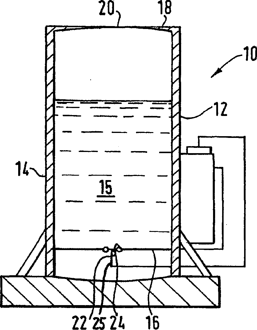
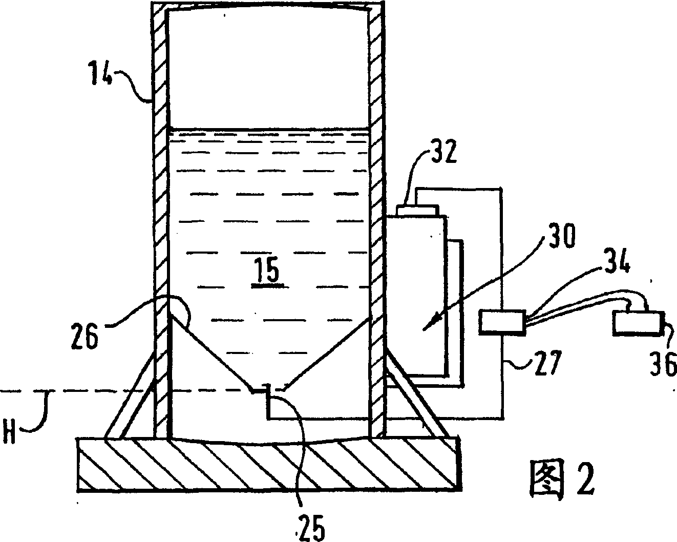
[0071] The 1-MCP / α-CD complex that 50g powdery concentration is 0.14% is put into the 1000ml beaker that 250ml water is housed, also put a Mini Jet MN404 submersible pump (from IPSD company, San Diego, California) in the beaker obtained), the flow rate was set at about 200 L / hr. The system was then placed in a 36L Plexiglas containment chamber fitted with a bulkhead for the insertion of gas sampling syringes. The temperature was set at 22°C.
[0072] After the chamber is sealed, the pump is turned on, creating a fountain of flow in the beaker. The release of 1-MCP was detected by air sampling in the sealed chamber at regular intervals. Analysis was performed by gas chromatography with a flame ionization detector.
[0073] For comparison, the above procedure was repeated twice without using the pump. The first comparative experiment involve...
Embodiment 2
[0090] This example shows the effectiveness of gas sparging to accelerate the release of 1-MCP in a small scale environment.
[0091]50 g of powdery concentration of 0.14% 1-MCP / α-CD complex was put into a 600 ml beaker with 250 ml of water, and a 10 inch long section of bubble wall air diffuser (IPSD, San Diego, California) was placed in the beaker. company). The air diffuser was connected to a Tetratec(R) air pump (Tetra Corporation, Blacksburg, VA) by a flexible connecting tube. The flow rate of the pump was set at 100 L / hr. The system was then placed in a 36L Plexiglas containment chamber fitted with a bulkhead for the insertion of gas sampling syringes.
[0092] After the chamber is sealed, the pump is turned on and the gas is bubbled through the aqueous suspension. The release rate of 1-MCP was detected by regularly sampling the air in the sealed chamber. Analysis was performed by gas chromatography with a flame ionization detector. The results are shown in Table 2....
Embodiment 3
[0103] This example shows the release of 1-MCP into a large scale environment such as a fruit storage warehouse using gas sparging.
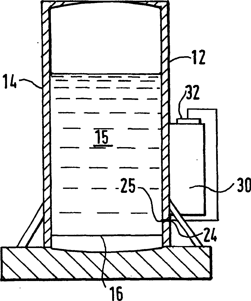
[0104] 3400 g of powdery concentration of 0.14% 1-MCP / α-CD complex was placed in a 20 L plastic container containing 11 L of water and a 56 inch long segment of a cell wall air diffuser (IPSD, Inc., San Diego, California). ). The air diffuser was connected to a Pro Gold(R) Profile 400 air pump by means of a flexible connecting tube. The air flow rate of the pump was set at 400 L / hr. The temperature was set at 22°C.
[0105] The container is covered and fitted with an outlet tube through which all escaping air must pass. After starting the pump, periodically sample the air exiting the vessel to determine the 1-MCP content. Analysis was performed by gas chromatography with a flame ionization detector. The results are shown in Table 3.
[0106] table 3
[0107] Time (hrs) Percentage of 1-MCP released
[0108] ...
PUM
 Abstract
Description
Claims
Application Information
 - R&D
- Intellectual Property
- Life Sciences
- Materials
- Tech Scout
- Unparalleled Data Quality
- Higher Quality Content
- 60% Fewer Hallucinations
Browse by: Latest US Patents, China's latest patents, Technical Efficacy Thesaurus, Application Domain, Technology Topic, Popular Technical Reports.
© 2025 PatSnap. All rights reserved.Legal|Privacy policy|Modern Slavery Act Transparency Statement|Sitemap|About US| Contact US: help@patsnap.com


