Foil gange deep sea insulation method and device

A strain gauge and deep-sea technology, applied in the direction of electromagnetic measuring devices, electric/magnetic solid deformation measurement, etc., can solve problems such as failure, damage to the mechanical properties of piles, strain gauges, and easy leakage detection of protective covers

Inactive Publication Date: 2003-11-26
INST OF MECHANICS - CHINESE ACAD OF SCI
View PDF0 Cites 6 Cited by
  • Summary
  • Abstract
  • Description
  • Claims
  • Application Information

AI Technical Summary

Problems solved by technology

At present, the main methods used at home and abroad are: 1. A variety of adhesives are covered and bonded, but this method fails to detect due to the aging of the adhesive; 2. Pre-weld the piles near the strain gauges, and then use the piles to buckle on the strain gauges A protective cover, the disadvantage of t

Method used


Image

  • Foil gange deep sea insulation method and device
  • Foil gange deep sea insulation method and device
  • Foil gange deep sea insulation method and device

Examples


Embodiment Construction

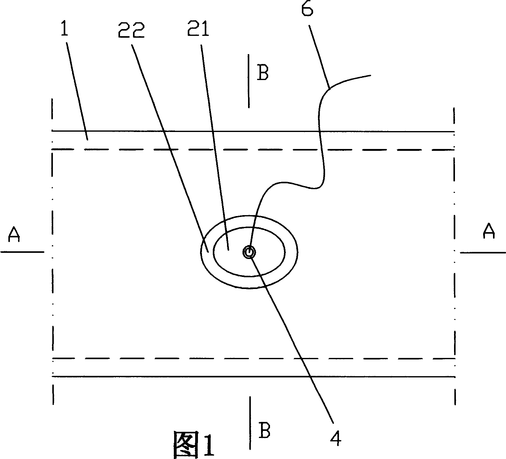
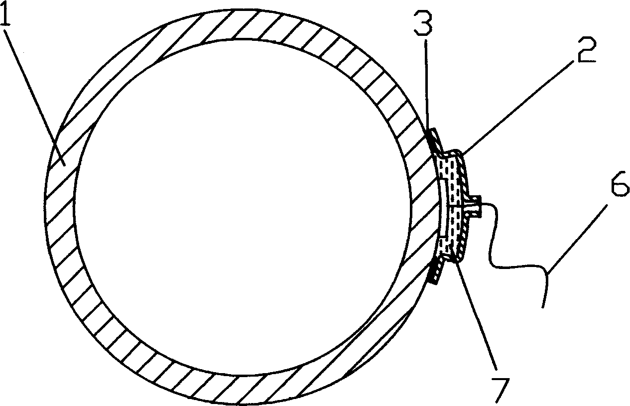
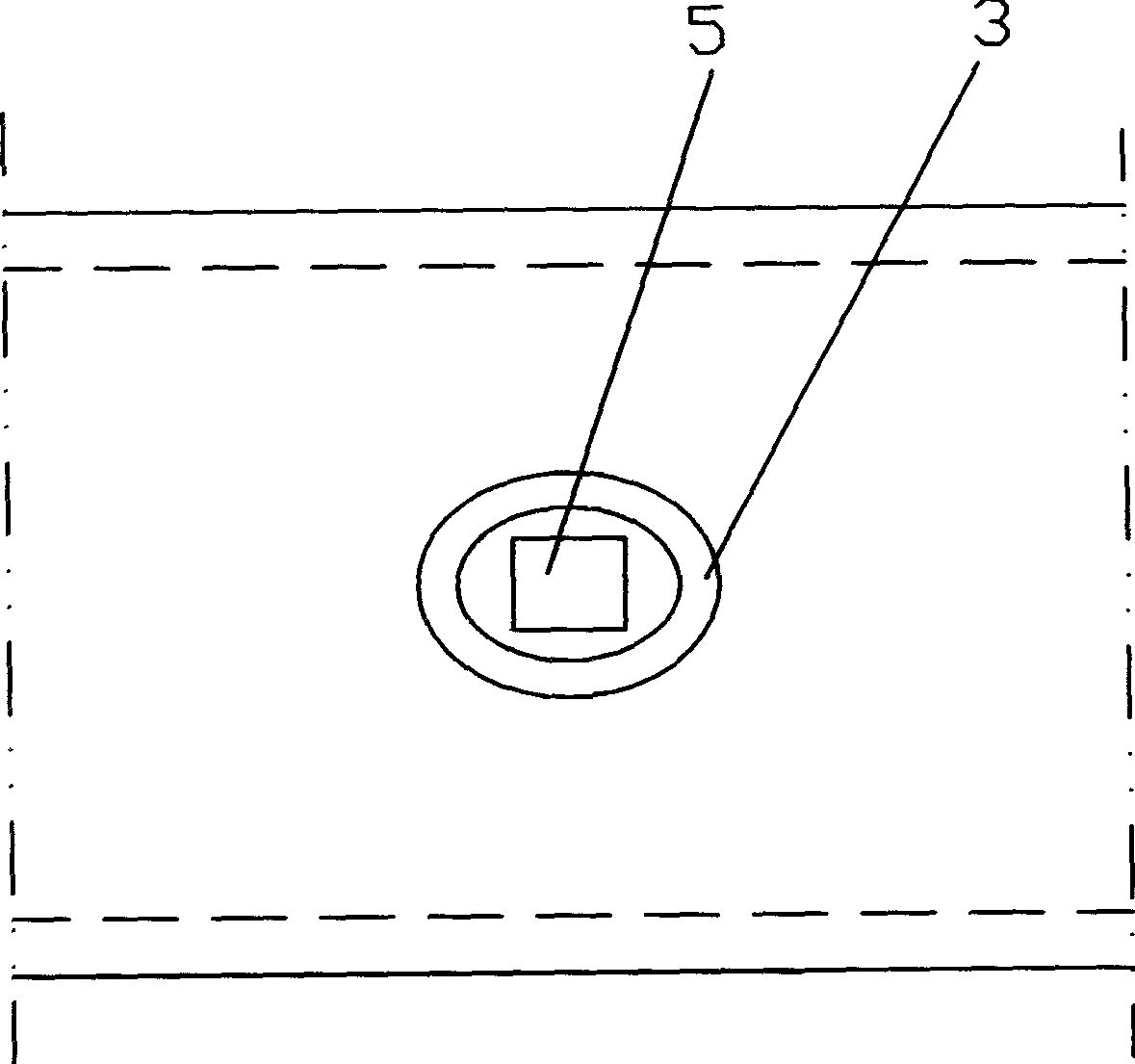
[0019] Figure 1 is a schematic diagram of a thin metal cover brazed on an offshore platform conduit. Part 1 is the conduit of the offshore platform, and Part 2 is a cover made of thin copper sheet. The thin copper cover includes a cover top 21 and a cover edge 22. The top of the cover is provided with a wire joint outlet 4. The shape of the bottom of the cover edge 22 is consistent with that of the offshore platform. The arc shape of the conduit 1 is adapted, and the bottom of the edge 22 of the cover is pre-coated with flux and covered with solder 3 . Such as figure 2 As shown, the strain gauge 5 is pasted on the conduit wall, and the periphery of the strain gauge is coated and covered with flux and solder. same. Fig. 3 is a sectional view along A-A in Fig. 1, Figure 4 It is a cross-sectional view along B-B in Fig. 1. The joint of wire 6 and the strain gauge are connected by general brazing, and the wire 6 passes through the outlet 4 of the wire joint of the cover 2. When...


PUM


Abstract

The present invention relates to the foil gage insulating method and device under deep sea condition. In the bottom edge of one thin metal hood comprising hood top and hood edge, one ring of brazingagent and soft brazing alloy in the same shape as that painted around the foil gage, and the hood has wire leading port in the top and bottom edge shape adaptive with the marine platform casing. after the thin metal hood covers onto the casing wall with adhered foil gage, the hood edge and the casing are brazed fast via heating. After the lead connected to the foil gage passes through the port,the port is sealed with high pressure sealing joint. Owing to the relatively low smelting point of the soft brazing alloy, the painting and brazing process has no influence on the mechanical performance of the casing wall and accurate measurement.

Description

technical field [0001] The invention relates to an insulation method and a device for a strain gauge, in particular to an insulation method and a device for a strain gauge in a deep sea environment. Background technique [0002] In the strain monitoring of the conduit wall of the offshore platform in the deep sea environment, the waterproof and insulating protection of the strain gauge is an important and difficult point. At present, the main methods used at home and abroad are: 1. A variety of adhesives are covered and bonded, but this method fails to detect due to the aging of the adhesive; 2. Pre-weld the piles near the strain gauges, and then use the piles to buckle on the strain gauges A protective cover, the disadvantage of this method is that the protective cover is easy to leak and the test fails, and when the pile is pre-welded, due to the high temperature, the mechanical properties near the pile will inevitably be destroyed, so that the measurement results of the s...

Claims


Application Information

Patent Timeline
IPC IPC(8): G01B7/16
Inventor 丁桦李岐
Owner INST OF MECHANICS - CHINESE ACAD OF SCI
Why Eureka
Try Eureka