Absolute pressure type pressure sensor

A pressure sensor, absolute pressure technology, applied in the direction of measuring fluid pressure, measuring fluid pressure through electromagnetic components, instruments, etc., can solve problems such as pressure sensor installation defects

Inactive Publication Date: 2003-12-03
NAGANO KEIKI
View PDF5 Cites 15 Cited by
  • Summary
  • Abstract
  • Description
  • Claims
  • Application Information

AI Technical Summary

Problems solved by technology

[0009] However, since the fluid introduction port 6 and the input / output port 7 are consistent in their directions, the hole 6 is formed along this direction and the input / exit port 7 is connected, so that there is a defect in the installation of the pressure sensor.

Method used


Image

  • Absolute pressure type pressure sensor
  • Absolute pressure type pressure sensor
  • Absolute pressure type pressure sensor

Examples


no. 1 approach

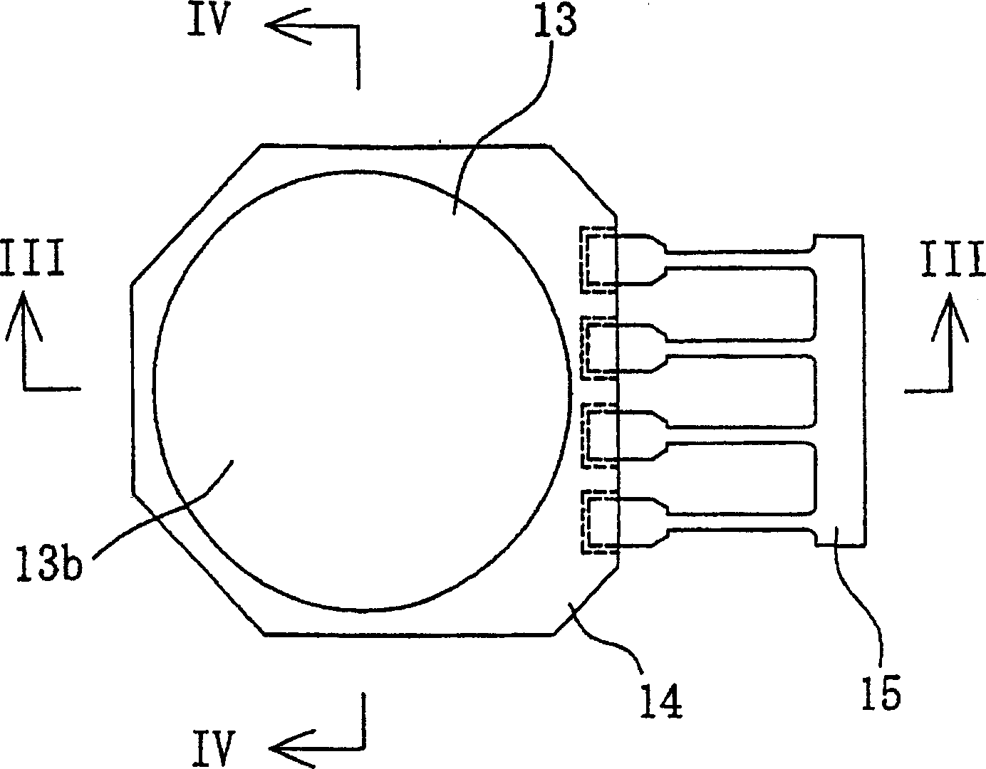
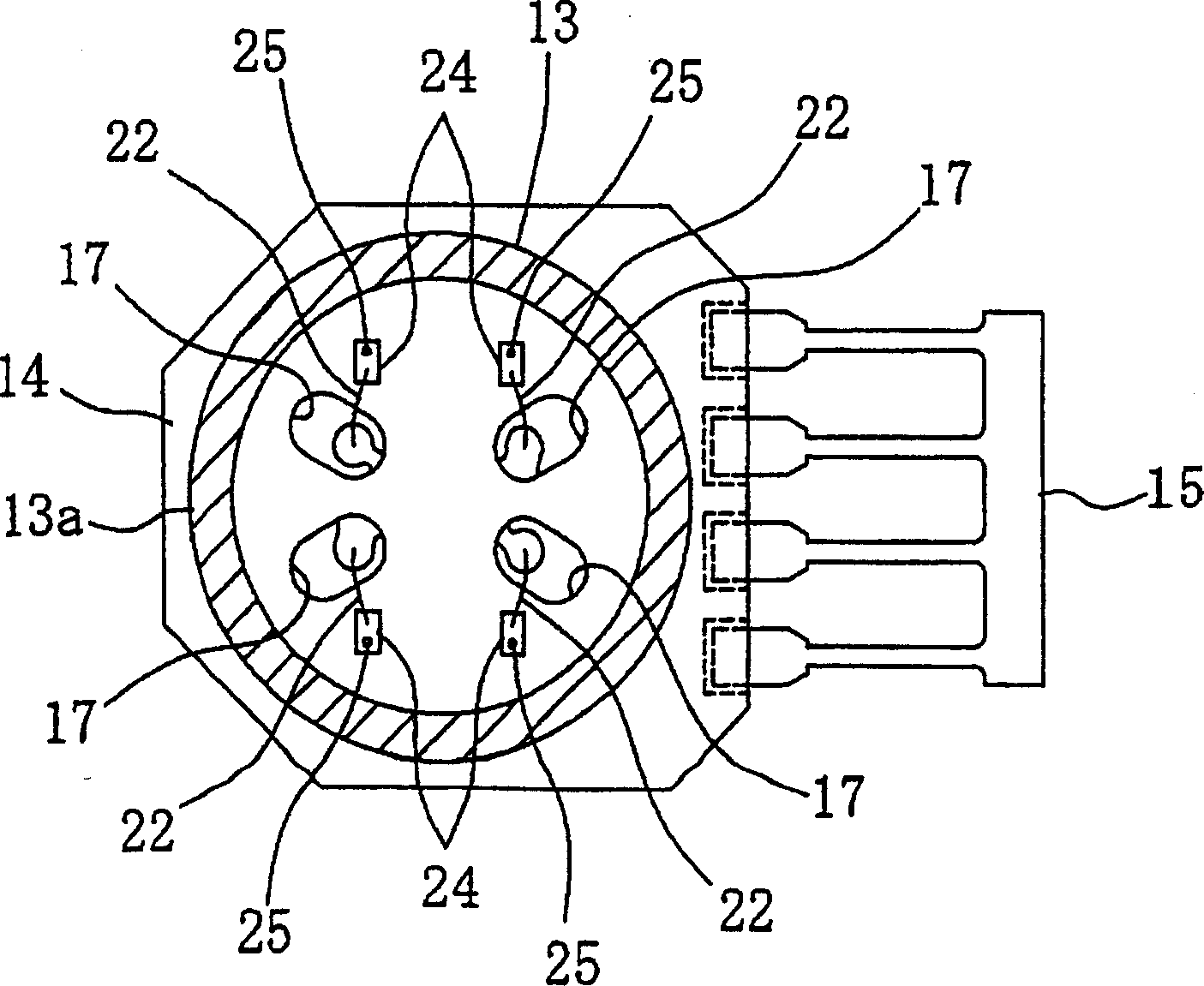
[0032] refer to Figures 1 to 4 , the first embodiment of the absolute pressure type pressure sensor will be described below.

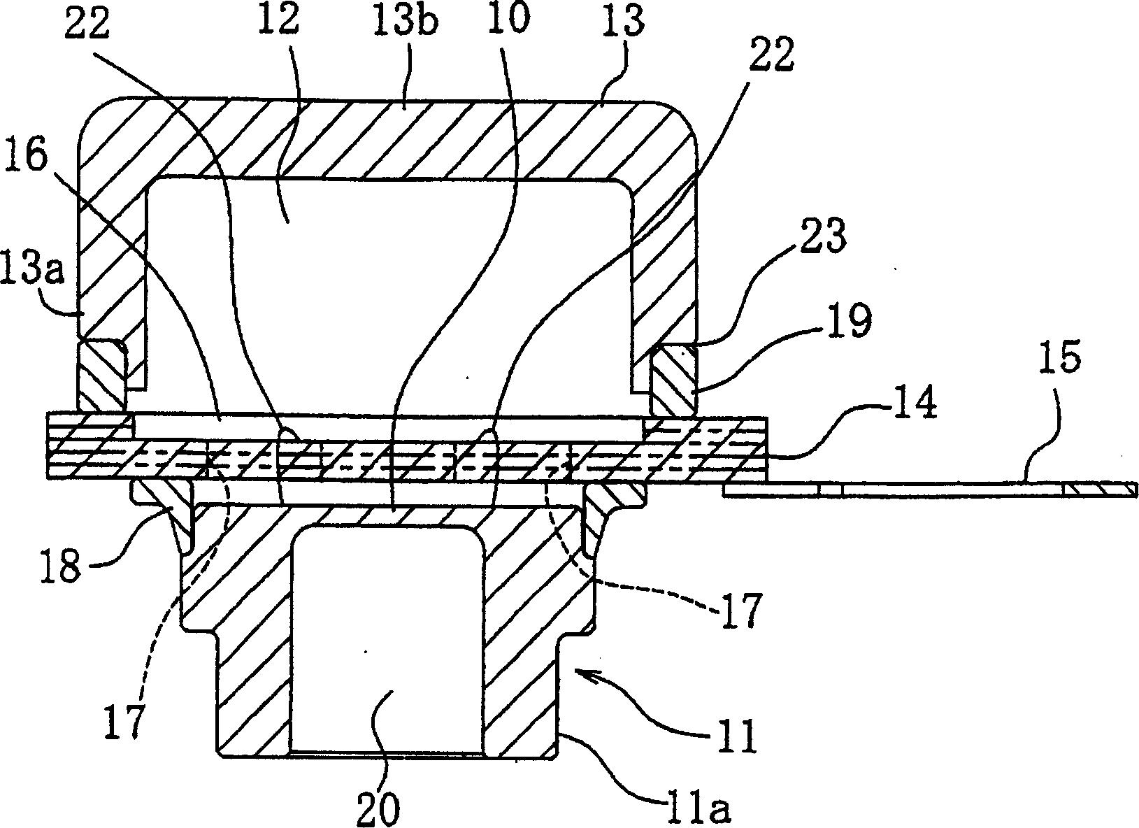
[0033] This absolute pressure type pressure sensor has a pressure measuring device 11 , a metal cover 13 , a relay board 14 and an input / output terminal 15 .

[0034] like image 3 and 4 As shown, among these members, the pressure measuring device 11 has a cylindrical part 11a with a metal film 10, and a strain gauge 9 is installed on one surface of the metal film 10 (such as Figure 10 as shown). The face on which the strain gauge is mounted is located on the side of the cylindrical member 11a opposite to the fluid introduction port 20 formed by the surface of the opposite side of the cylindrical member 11a. A metal cover 13 is provided to form a reference pressure space 12 surrounding the strain gauge 9 placed on the metal membrane 10 . The relay plate 14 is electrically connected not only to the strain gauges 9 but also to the I / O terminals 15...

no. 2 approach

[0053] refer to Figures 5 to 8 , an absolute pressure type pressure sensor according to a second embodiment of the present invention will be described below.

[0054] The absolute pressure type pressure sensor in this embodiment is equipped with a relay board 26 different from that in the first embodiment. In particular, the relay board 26 is not provided with a cavity on the relay board 14 as in the first embodiment. Therefore, both surfaces of the relay board 26 are flat, so that its manufacturing process can be simplified compared with that of the relay board 14 in the first embodiment.

[0055] Other components and production are completely consistent with those in the first embodiment, and the reference numerals shown are also the same as those in the first embodiment, and their detailed descriptions are omitted here.


PUM


Abstract

An absolute-pressure type of pressure sensor is provided. The sensor has a pressure detecting device having a metal diaphragm. Strain gauges are disposed on one surface of the diaphragm, whose other surface is formed to receive fluid to be detected. The sensor comprises a lid, relay board, two seal rings, and input / output terminal. The lid provides a reference pressure space. The relay board is electrically connected to the gauge and composed of laminated ceramic members having both of through holes formed to pass through both sides thereof and a protrusion formed outwardly. The two seal rings are located to face the two sides of the board, respectively. The one seal ring air-tightly connects the relay board and the diaphragm. The other seal ring air-tightly connects the relay board and the lid. The terminal is electrically connected to the relay board and mounted on the protrusion of the relay board.

Description

Background of the invention [0001] The invention relates to a pressure sensor, in particular to an absolute pressure type pressure sensor capable of measuring absolute pressure values. [0002] In general, various forms of absolute pressure type pressure sensors are known. Among these sensors, Japanese Patent Publication (Unexamined) No. 1998-90096 (Reference Document 1) and Japanese Patent Publication (Unexamined) No. 1999-83655 (Reference Document 2) disclose an absolute Pressure type pressure sensor, in this type of sensor, the diffused semiconductor type pressure sensitive chip is packaged liquid-tight with a film, so that the package liquid can prevent the fluid from contacting the sensor chip. [0003] Another Japanese Patent Publication (Unexamined) No. 1999-295174 (Reference Document 3) also discloses an absolute pressure type pressure sensor. This pressure sensor utilizes a metal pressure cell as the cover. Such a pressure cell forms a reference pressure space (vac...

Claims


Application Information

Patent Timeline
Patent Type & Authority Applications(China)
IPC IPC(8): G01L9/04G01L9/00
CPCG01L19/146G01L19/0084G01L19/0061G01L19/143G01L19/148
Inventor 金子嘉一长坂宏
Owner NAGANO KEIKI
Why Eureka
Try Eureka