Method and apparatus for measuring vector distance on lead wire connector

A technology of wire bonding and bonding head, which is applied in the field of devices, and can solve problems such as the distance change between the capillary and the image recognition system

Inactive Publication Date: 2003-12-03
ESEC TRADING
View PDF2 Cites 2 Cited by
  • Summary
  • Abstract
  • Description
  • Claims
  • Application Information

AI Technical Summary

Problems solved by technology

However, there is a problem in the process of operation, that is, the distance between the capillary and the optical axis of the image recognition system will change unpredictably due to thermal effects

Method used


Image

  • Method and apparatus for measuring vector distance on lead wire connector
  • Method and apparatus for measuring vector distance on lead wire connector
  • Method and apparatus for measuring vector distance on lead wire connector

Examples


Embodiment Construction

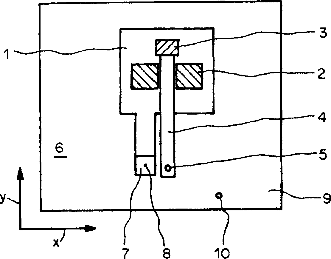
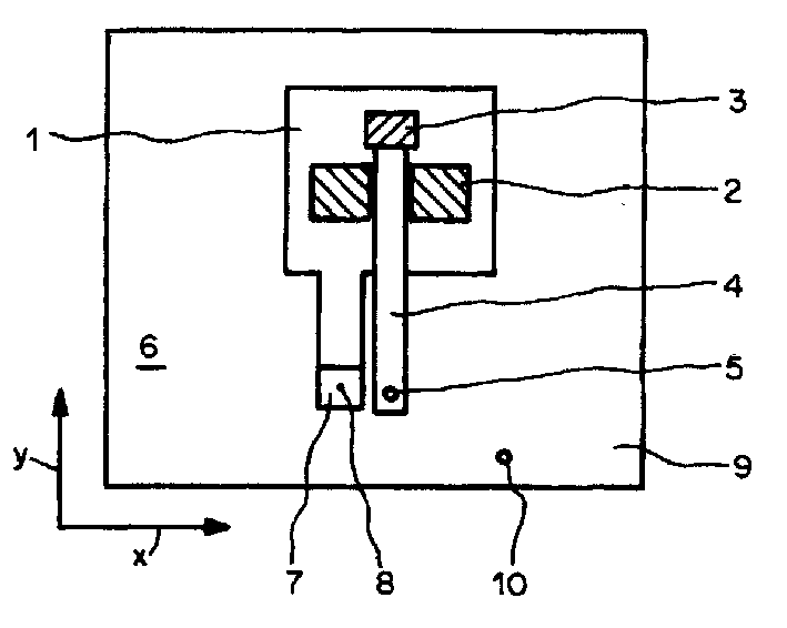
[0014] figure 1 A plan view of a bonding head 1 of a wire bonder is shown. The joint head 1 contains a rocker 2 that can rotate on a horizontal axis. An angle 4 is connected to the rocking rod 2, and the ultrasonic transducer 3 can apply ultrasonic waves to it. A capillary 5 is clamped at the tip of the horn 4 . The capillary 5 is used to fix the leads to the connection points on the semiconductor chip and to the designated connection points on the substrate, while guiding the wiring between the two connection points. The bonding head 1 can move the capillary 5 on a plane 6 determined by two coordinate axes x and y, and the rocker 2 can move the capillary in a direction perpendicular to the plane 6 . In addition, the wire bonder also includes an image recognition system with its observation area facing the plane 6 for measuring the position of the connection points on the semiconductor chip and the connection points on the substrate. The image recognition system includes a...


PUM

PropertyMeasurementUnit
diameteraaaaaaaaaa

Abstract

To determine the vectorial distance D between the tip of a capillary and an optical axis of an image recognition system of a Wire Bonder, a glass fibre supplied with light is used as a reference point and as a sensor. On the one hand, the glass fibre serves as a reference point with which the position of the optical axis of the image recognition system can be determined. On the other hand, the glass fibre serves as a sensor with which the position of the tip of the capillary can be determined in that it is determined at which position of the bondhead the intensity of the light which is reflected back into the glass fibre by a wire ball formed at the tip of the capillary is at a maximum.

Description

Technical field: [0001] The invention relates to a method for determining the vector distance between a capillary of a wire bonder and its image recognition system, and a device for this purpose in a wire bonder. Background technique: [0002] A wire bonder is an automatic machine used to wire semiconductor chips on a substrate after assembly. The wire bonder has a capillary on it that is clipped on the tip of a horn. This capillary is used to fix the lead wire to a connection point on the semiconductor chip and to a connection point on the substrate while guiding wiring between the two connection points. In order for the capillary to touch the correct position on the connection point, the positions of the two connection points must be determined by an image recognition system before connection. However, there is a problem during operation that the distance between the capillary and the optical axis of the image recognition system will change unpredictably due to thermal e...

Claims


Application Information

Patent Timeline
Patent Type & Authority Applications(China)
IPC IPC(8): B23K20/00B23K20/26G06T7/00H01L21/00H01L21/607
CPCH01L2224/85205H01L2924/01027B23K20/005H01L24/78H01L2924/01005G06T7/004H01L2924/01082H01L2924/01039B23K20/26H01L2924/01066H01L21/67138B23K2201/40B23K20/007H01L2224/78301H01L2924/01006H01L2924/01033H01L2924/00014H01L2924/01075G06T7/70B23K2101/40H01L2224/48H01L2224/45099H01L21/60
Inventor 彼得·赫斯马库斯·米切勒尼考里诺·昂达
Owner ESEC TRADING
Why Eureka
Try Eureka