Optical device for simulating satellite trail

A technology of satellite trajectory and optical simulation, applied in active electrical relay systems, transmission monitoring, electrical components, etc. Effect

Inactive Publication Date: 2003-12-24
SHANGHAI INST OF OPTICS & FINE MECHANICS CHINESE ACAD OF SCI
View PDF0 Cites 21 Cited by
  • Summary
  • Abstract
  • Description
  • Claims
  • Application Information

AI Technical Summary

Problems solved by technology

Since this solution is directly driven by the motor to move the satellite optical communication system, it occupies a l

Method used


Image

  • Optical device for simulating satellite trail
  • Optical device for simulating satellite trail
  • Optical device for simulating satellite trail

Examples


Embodiment 2

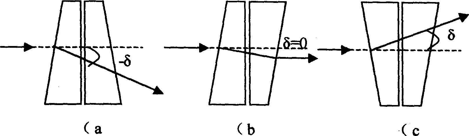
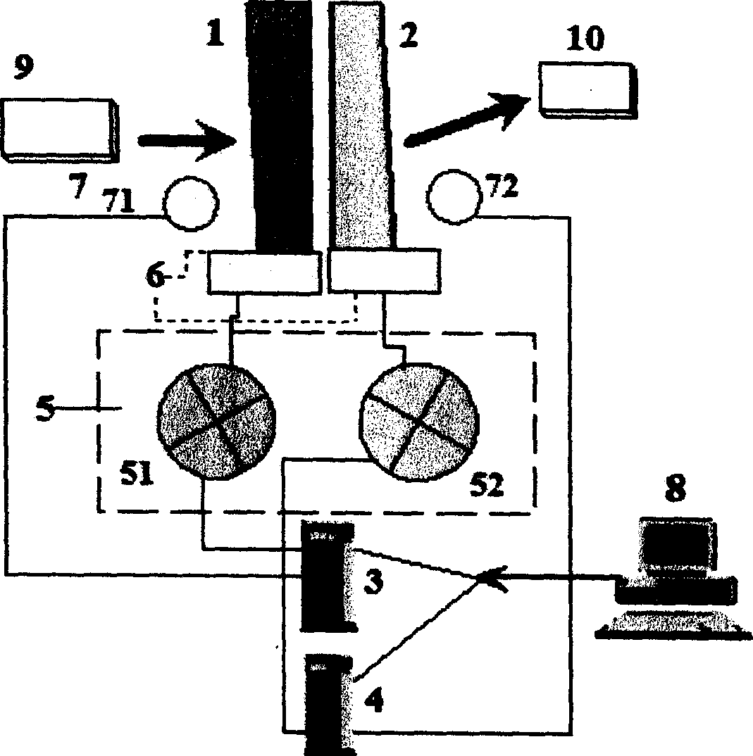
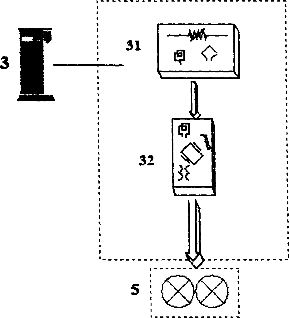
[0039] Embodiment 2: use motor group 5 to control double prism 1, the scheme of 2 rotations, namely motor 51 controls double prism 1, 2 to rotate in the same direction, and motor 52 controls double prism 1, 2 to rotate in the opposite direction, select new mechanical The transmission mechanism (new gear sets 61, 62), starts the new optical simulation device control program 83 part, and selects the closed-loop control system. See attached Figure 5 , 6 .

Embodiment 3

[0040] Embodiment 3: adopt the scheme that motor group 5 drives double prism 1,2 respectively, namely motor 51 drives double prism 1 to rotate, and motor 52 drives double prism 2 to rotate, there is no angular displacement sensor 7 in the device, other is the same as the best embodiment, This constitutes an open-loop control system with a simple structure and can be used for demonstration, see Figure 7 .

Embodiment 4

[0041] Embodiment 4: use motor group 5 to control double prism 1, the scheme of 2 rotations, namely motor 51 controls the unified rotation of double prism 1, 2, and motor 52 controls the relative rotation between double prism 1, 2, selects new mechanical transmission for use Mechanism (new gear sets 61,62, and fixed parts 63,64), start the new optical simulation device control program 83 parts, there is no angular displacement sensor 7 (71,72) in the device, other is the same as embodiment 2, select open Ring control system, simple structure, can be used for demonstration, see attached Figure 8 .


PUM


Abstract

The device is utilized for measuring the parameters in the procedure of trailing satellites between the synchronous orbit and the low orbit. The device is composed of the three parts: the optical assembly, the electromechanical system and the computer control system. The usage of the device includes testing the trailing parameters, validating performances and evaluation of the satellite laser communication system from earth based laboratory. Meanwhile, the device provides an experimental analysis of feasibility of new technical executive plan for developing satellite laser communication system. The invention features simple structure, high practicability and accuracy. The device can generate 2D motion track and small floor space etc.

Description

technical field [0001] The invention relates to laser communication, in particular to a satellite trajectory optical simulation device. The device will be used in the ground laboratory for the satellite laser communication system to test the parameters of tracking and performance verification and evaluation, etc. It can also provide the experimental analysis results of the possibility of implementing a new technology for the development of the satellite laser communication system . Background technique [0002] Compared with radio frequency radio technology, space optical communication technology has many advantages and great potential for development, which has achieved the consensus of many experts and scholars in the field of communication. Space optical communication technology refers to the use of laser beams as information carriers to realize communication between two application space targets. Applied space targets include satellites in geosynchronous orbits, medium...

Claims


Application Information

Patent Timeline
IPC IPC(8): H04B7/15H04B10/11
Inventor 祖继锋刘立人云茂金滕树云栾竹孙建锋
Owner SHANGHAI INST OF OPTICS & FINE MECHANICS CHINESE ACAD OF SCI
Why Eureka
Try Eureka