
Demodulation timing generation circuit and demodulation apparatus

A technology for generating circuits and circuits, applied in the direction of electrical components, modulated carrier systems, multiplexed communications, etc.

Inactive Publication Date: 2003-12-31
SONY CORP
View PDF0 Cites 4 Cited by
  • Summary
  • Abstract
  • Description
  • Claims
  • Application Information

AI Technical Summary

Problems solved by technology

[0022] In the best systems, retransmission of data will be achieved, however if one expects to guarantee a certain level of QoS (Quality of Service), this will be a fatal problem

Method used


Image

  • Demodulation timing generation circuit and demodulation apparatus
  • Demodulation timing generation circuit and demodulation apparatus
  • Demodulation timing generation circuit and demodulation apparatus

Examples


no. 1 example

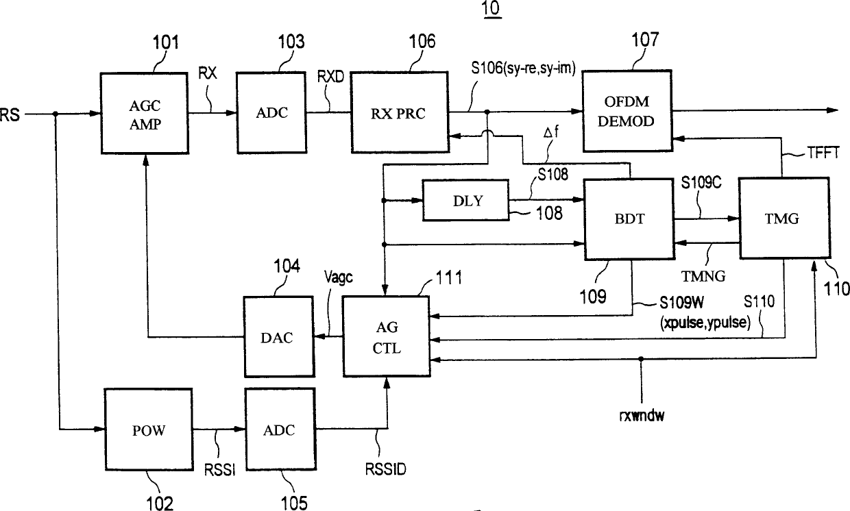
[0118] 1 is a block diagram showing the structure of a first embodiment of a burst synchronous demodulation apparatus to which an FFT timing generating circuit according to the present invention is applied.

[0119] As shown in Figure 1, the main components that burst pulse synchronous demodulation device 10 comprises are: automatic gain control amplifier (AGCAMP) 101, received signal power monitor (POW) 102, analog / digital (A / D) converter ( ADC) 103, digital / analog (D / A) converter (DAC) 104, A / D converter (ADC) 105, received signal processing unit (RXPRC) 106, OFDM demodulator (DEMOD) 107, delay unit ( DLY) 108, Burst Detector (BDT) 109, Timing Controller (TMG) 110 and Amplification Gain Controller (AGCTL) 111.

[0120] The automatic gain control system of the burst pulse synchronous communication system adopted in the present embodiment, transmission (reception) signal, and FFT timing optimization overview will be described in order below, and the burst pulse synchronous dem...

no. 2 example

[0402] Fig. 26 is a block diagram showing the structure of a second embodiment of a burst synchronous demodulation apparatus to which the FFT timing generating circuit according to the present invention is applied. Also, FIG. 27 is a circuit diagram of a specific structural example of the burst detector and timing controller of FIG. 26 according to the second embodiment of the present invention.

[0403] The second embodiment differs from the first embodiment explained above in that a frame synchronization function is added to the burst detector and the timing controller.

[0404] Specifically, in the second embodiment, by calculating the cross-correlation between the frame synchronization data (already known) and the input data, detection is performed only for the peak value that is in the detection window and exceeds the detection threshold, and after the synchronization is established according to The detection window is set by the frame period counted by the reference cloc...


PUM


Abstract

A demodulation timing generation circuit capable of generating correctly and with high precision a timing for demodulating a reception signal even under various kinds of reception conditions and a demodulation apparatus using the same, wherein AGC control and frequency offset correction are performed by the burst detector 109 and the amplification gain controller 111 using a synchronization training signal (burst signal) added to the head of the reception signal (packet), a detection window period is provided for cross-correlation detection to detect the peak of the cross-correlation in the detection window DW by the timing controller 110, and in the end (rear edge) of the window, data corresponding to the peak position is loaded in the counter 11003 for counting the OFDM symbol interval. Due to this, it is possible to set an optimal FFT timing irrespective of the condition of a channel.

Description

technical field [0001] The present invention relates to a demodulation timing generation circuit and a demodulation device for a receiver of a wireless communication system, and more particularly to a demodulation device for receiving signals modulated by, for example, an Orthogonal Frequency Division Multiplexing (OFDM) modulation method and including burst pulses. A demodulation timing generating circuit and a demodulation device of a wireless communication system such as a burst signal including a preamble signal at the head of a packet signal modulated here. Background technique [0002] The OFDM modulation method is for 2 n The signal symbols sent by the basic modulation (QPSK, 16ASAM, etc.) are inversely Fourier transformed to form 2 orthogonal to each other on the frequency axis. n A modulation method of subcarriers. [0003] In a wireless communication system employing such an OFDM modulation system, a transmitter serial-to-parallel converts transmission data, and ...

Claims


Application Information

Patent Timeline
Patent Type & Authority Applications(China)
IPC IPC(8): H04J11/00H04B7/26H04L7/10H04L27/26
CPCH04L27/2656H04L27/2662H04L27/2675
Inventor 若松正孝
Owner SONY CORP
Learn More