Position calculation method and a mobile terminal and a server therefor

A measurement method and terminal technology, which is applied to beacon systems, instruments, and positioning using radio waves, and can solve problems such as multi-steps, storage capacity, and limitations on the number of codes to be sent

Inactive Publication Date: 2004-01-14
MAXELL HLDG LTD
View PDF5 Cites 5 Cited by
  • Summary
  • Abstract
  • Description
  • Claims
  • Application Information

AI Technical Summary

Problems solved by technology

However, generating a delay profile for a send code requires many steps and memory
Therefore, the number of transmission codes of the base station that can generate a delay profile is limited from the viewpoint of circuit scale
This limit will be stricter if the miniaturization of the terminal and power saving are pursued

Method used


Image

  • Position calculation method and a mobile terminal and a server therefor
  • Position calculation method and a mobile terminal and a server therefor
  • Position calculation method and a mobile terminal and a server therefor

Examples


Embodiment Construction

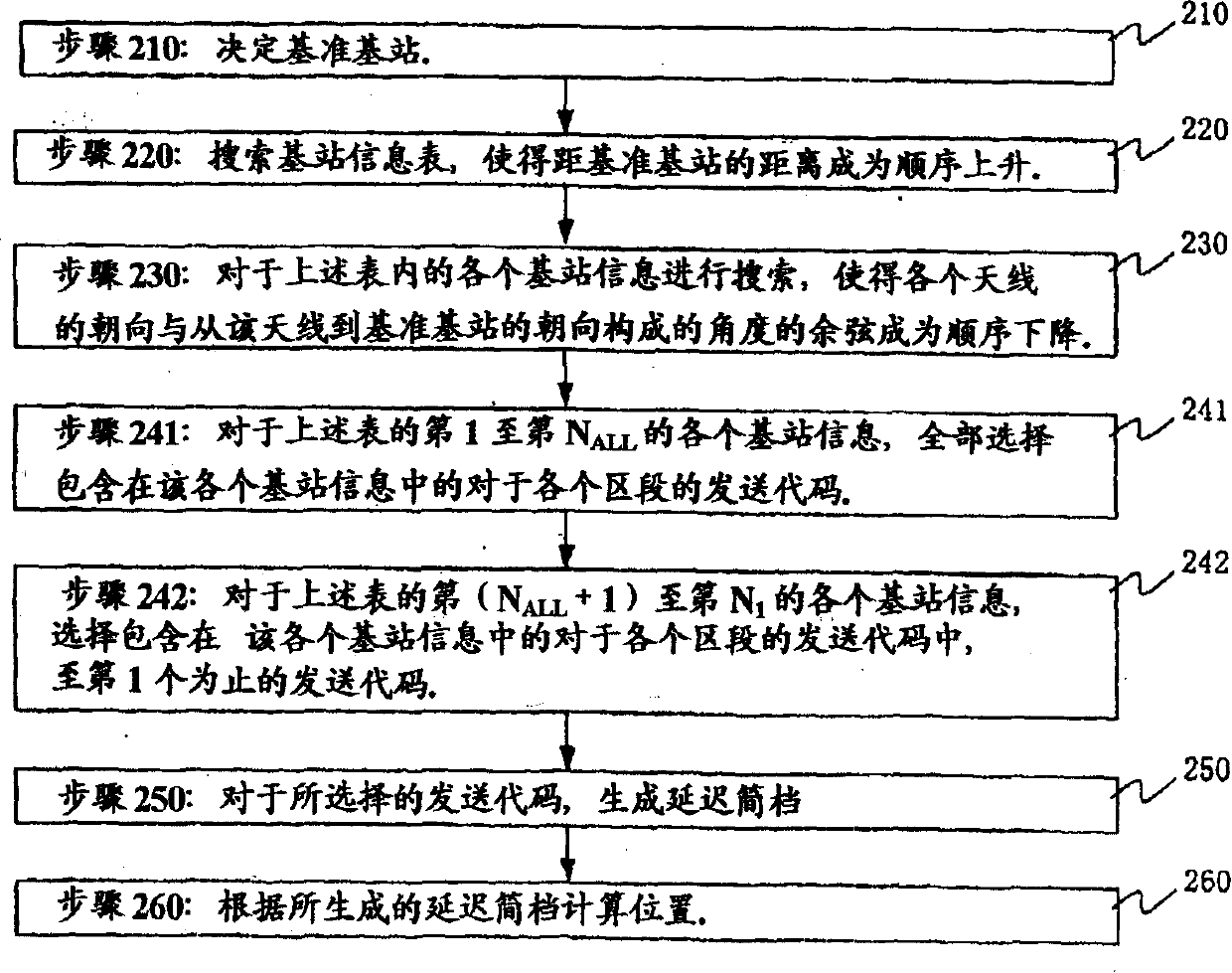
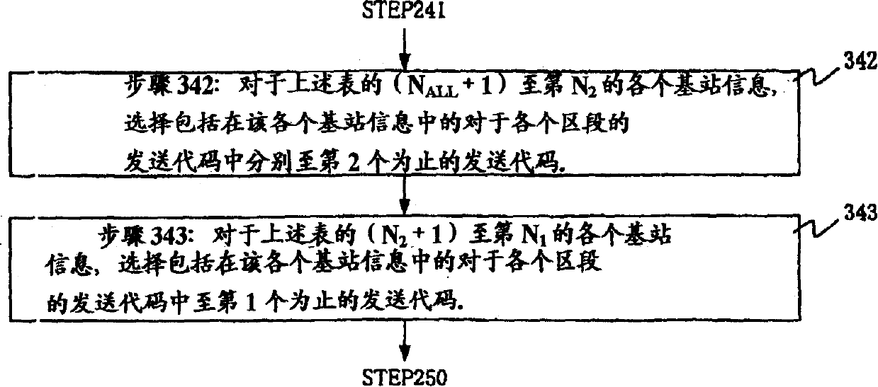
[0043] In the wireless position measurement method based on the generation of the delay profile of the received signal according to the present invention, the base station corresponding to the generation target of the delay profile is selected based on the position of the base station and the orientation of each antenna of the base station forming each segment. The sending code for the segment. Hereinafter, specific examples of the present invention will be described using the drawings.

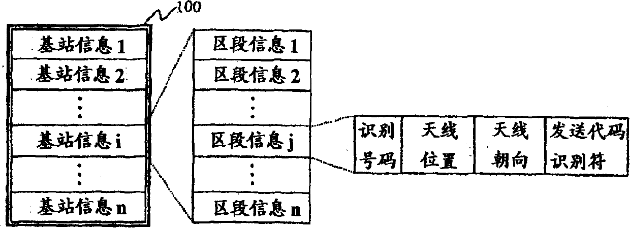
[0044] An example of using the base station information table in the present invention will be described with reference to FIG. 1 . In the figure, 100 is a base station information table. The table includes a plurality of base station information 1 to n. Each piece of base station information includes one or more pieces of section information. Each segment information includes the position of the antenna for forming the identification number and the segment, the orientation of the antenna,...


PUM


Abstract

In calculation of a position of a terminal (Fig. 9), there arises, when creating a delay profile (FIG. 13), a problem to select a transmission code for a sector of a base station (FIGS. 17 and 18) to create the delay profile. According to a position of a base station and a bearing of each antenna (FIG. 17) forming a sector of the base station (230), a wireless position calculation method selects a transmission code for a sector of a base station to create a delay profile (242). Under a condition that the number of delay profiles to be created is limited, each delay profile is created in consideration of the antenna bearing. Therefore, the number of base stations at mutually different positions is increased to calculate the position and precision calculation is improved (FIG. 17).

Description

technical field [0001] Field of the Invention This invention relates to location determination by wireless, and more particularly to techniques using cellular base stations as signal sources. Background technique [0002] Among terminal position measurement techniques using broadband wireless signals, a system using CDMA (Code Division Multiplexing) signals is disclosed in US Patent Application No. 09 / 791862. [0003] Figure 12 shows its concept. Terminal 1201 receives signals (transmission codes) transmitted from a plurality of synchronized base stations 1202, 1203, and 1204 via GPS (Global Positioning System) 1205, etc., and generates a delay profile indicating signal reception timing. Also, the transmission distance is inferred from the delay profile, and the terminal location is inferred from the known base station location and the inferred distance. [0004] Figure 13 shows an example of a delay profile. The so-called delay profile is the result of calculating the co...

Claims


Application Information

Patent Timeline
Patent Type & Authority Applications(China)
IPC IPC(8): G01S1/04G01S5/14H04B1/707H04B1/7113H04W16/24H04W16/28H04W60/00H04W64/00
CPCH04W64/00G01S1/045G01S5/14H04W16/24
Inventor 荻野敦藤嵨坚三郎铃木秀哉
Owner MAXELL HLDG LTD
Why Eureka
Try Eureka