Prepn process and device of continuously variable light attenuating plate

A technology of attenuation sheet and glass substrate, which is applied in the field of preparation and realization of optical continuous variable attenuation sheet

A technology of attenuation sheet and glass substrate, which is applied in the field of preparation and realization of optical continuous variable attenuation sheet

CN1469179AInactive Publication Date: 2004-01-21GUANGXUN SCI & TECH WUHAN

Image

  • Prepn process and device of continuously variable light attenuating plate
  • Prepn process and device of continuously variable light attenuating plate
  • Prepn process and device of continuously variable light attenuating plate

Examples


Embodiment Construction

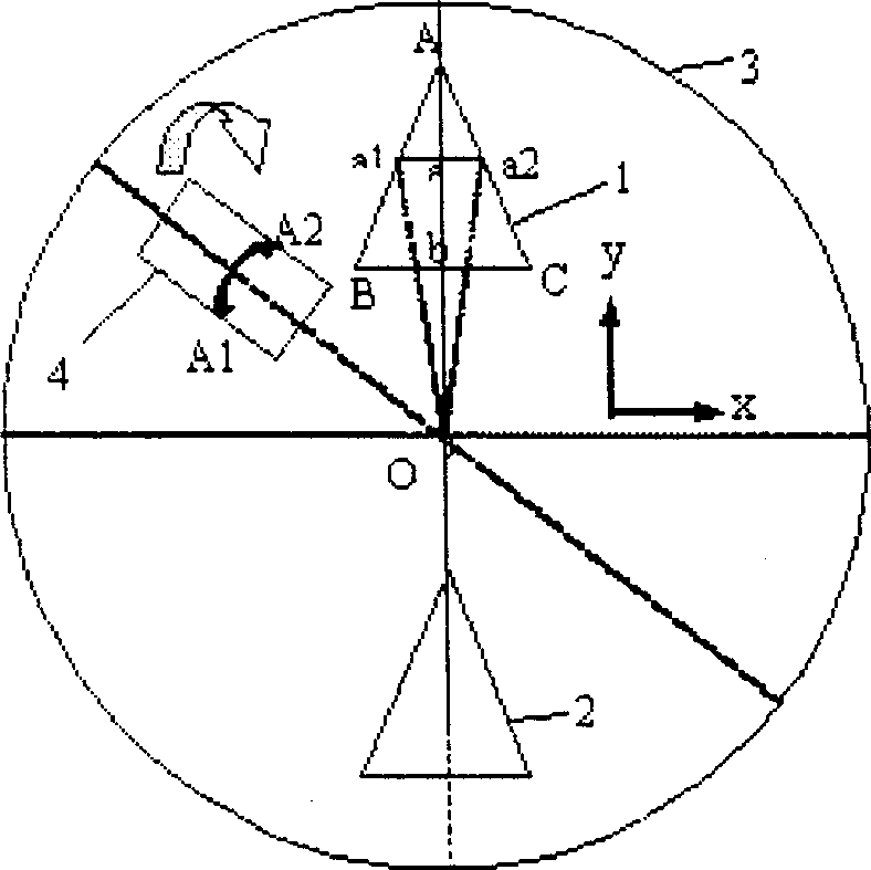
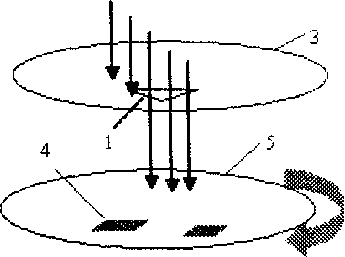
[0016] Combined with the structure of the vacuum chamber of the sputtering equipment, a circular deposition baffle 3 is designed, and a deposition hole with a certain pattern is dug on it. The top corner of the deposition hole 1 is facing away from the rotation axis O of the bottom plate 5, as figure 1 shown. The relative positions of sputtering deposition baffle plate 3, glass substrate 4 and base plate 5 in the vacuum chamber of the sputtering equipment are as follows: figure 2 As shown, the deposition baffle 3 and the bottom plate 5 are coaxial, the glass substrate 4 is placed on the bottom plate 5, the deposition hole 1 is located directly above the glass substrate 4, and the glass substrate 4 moves in a circle around the axis. The attenuator is deposited by DC sputtering, and the attenuation linearity is required to be L=ky, where L is the attenuation loss and y is the length of the attenuator. First measure the distribution of the target, and select a region with a rel...


PUM


Abstract

The present invention relates to one method and device of realizing control light change on glass substrate. One sputtering deposition baffle with special pattern for compensating target distribution is designed based on the film thickness distribution curve of sputtered target material, so that one layer of attenuating metal film with thick variation is deposited on the glass substrate. When the incident light shifts in the gradually varying film thickness direction, the intensity of the transmitted light changes continuously to realize the continuous attenuation of light. Thus prepared attenuating plate has excellent attenuation linearity. The said method may be used in preparing attenuating plate of different attenuation slope and different attenuating range, and is simple in operation and low in cost.

Description

technical field [0001] The invention relates to a method for realizing continuous variable light on a glass substrate and related realization devices. Background technique [0002] The optical attenuators currently used in optical communication systems are mainly based on the following technologies: 1) electromagnetic or thermo-optic crystals, which control electrical or thermal signals to change the transmission characteristics of light, 2) placing lenses between optical fibers to change the lens 3) insert an attenuation sheet formed of a metal material between the optical fibers. For the third technology, its core component, the attenuation sheet, is generally prepared by sputtering or thermally evaporating one or more layers of metal film on a glass substrate, such as "Light attenuation element" EP0165015, MATSUMARA FUMIO In the introduction, a layer of chromium Cr film and nickel Ni film are thermally evaporated on the glass substrate respectively...

Claims


Application Information

Patent Timeline
21 Jan 2004
Publication
CN1469179A
IPC
G02F1/17
Inventors
陈思乡; 孙晓斌