Wet type dual-collecting and fume purifying apparatus

A technology of flue gas purification and wet dust removal, which is applied in chemical instruments and methods, separation of dispersed particles, and the use of liquid separation agents, etc. It can solve the problems of not being too high in wind speed, lowering the bottom purification efficiency, and carrying water.

Inactive Publication Date: 2004-01-28
杨长明
View PDF0 Cites 15 Cited by
  • Summary
  • Abstract
  • Description
  • Claims
  • Application Information

AI Technical Summary

Problems solved by technology

Although the foam dust collector has the advantages of simple structure and low cost, the foam layer is unstable and has certain requirements on the wind speed. If the wind speed does not meet the requirements, it will be difficult to build a foam

Method used


Image

  • Wet type dual-collecting and fume purifying apparatus
  • Wet type dual-collecting and fume purifying apparatus
  • Wet type dual-collecting and fume purifying apparatus

Examples


Embodiment 1

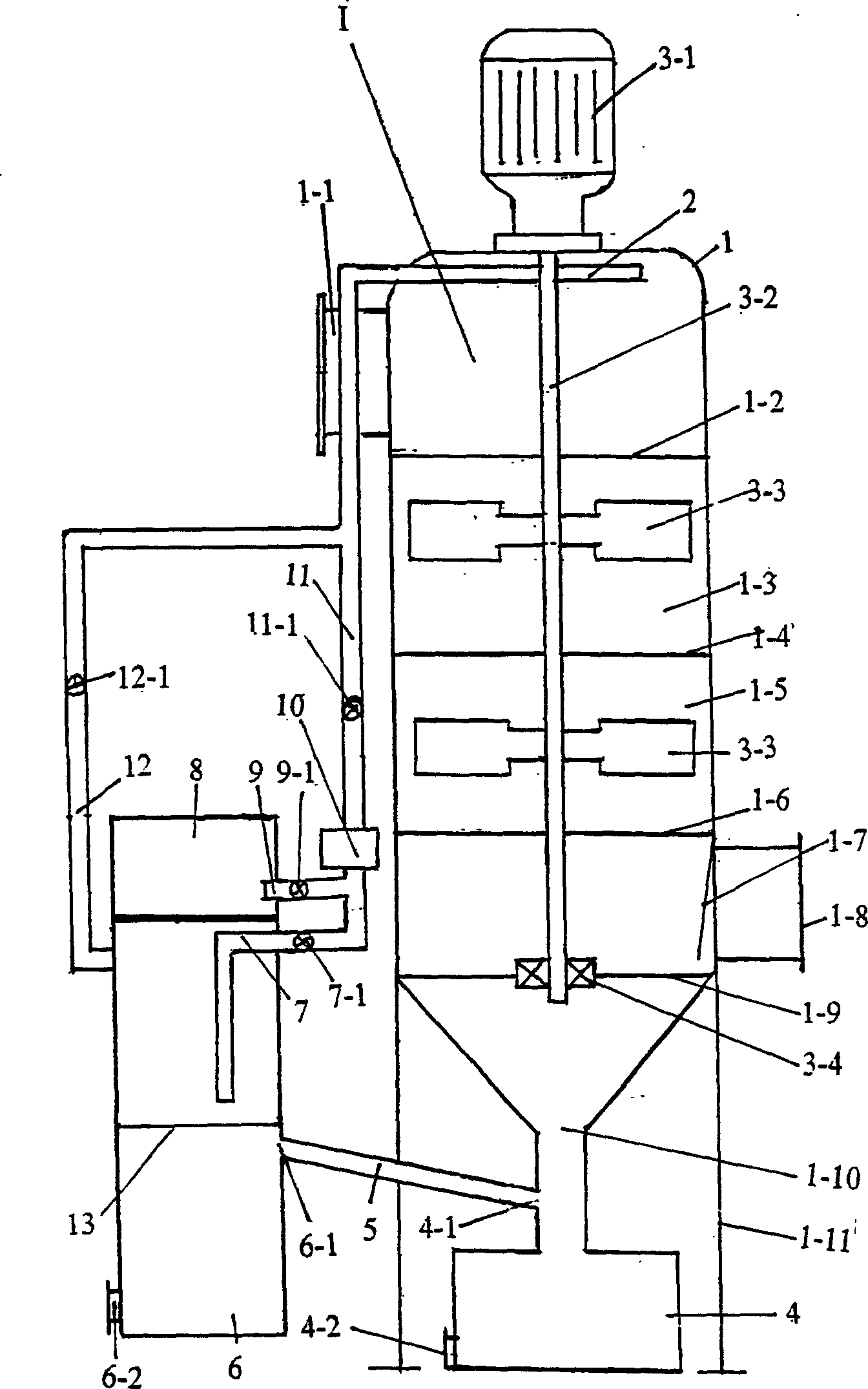
[0019] Example 1 has a foam purifier I, which is fixed by support brackets 1-9. The inlet and outlet ports 1-1 and 1-8 of the foam purifier 1 are respectively arranged on the upper and lower parts of the cylinder body 1, and the dust outlet 1-10 is arranged at the bottom of the cylinder body. The smoke inlet 1-1, that is, the upper part is provided with a sprayer 2, the nozzle of the sprayer 2 is directed downward, and the lower part of the sprayer 2 is provided with upper and lower mesh plates 1-2, 1-6, upper and lower mesh plates 1-2, The distance between 1-6 depends on the amount of exhaust gas and the dust concentration, which can reach 2 to 3 meters. The space between the two mesh panels 1-2 and 1-6 is the foam chamber. The middle screen plate 1-4 is arranged between the lower screen plates 1-2 and 1-6. The upper, middle and lower screen plates divide the interior of the purification cylinder 1 into 4 chambers. The two middle chambers 1-3 and 1-5 are: In the foam chamber...

Embodiment 2

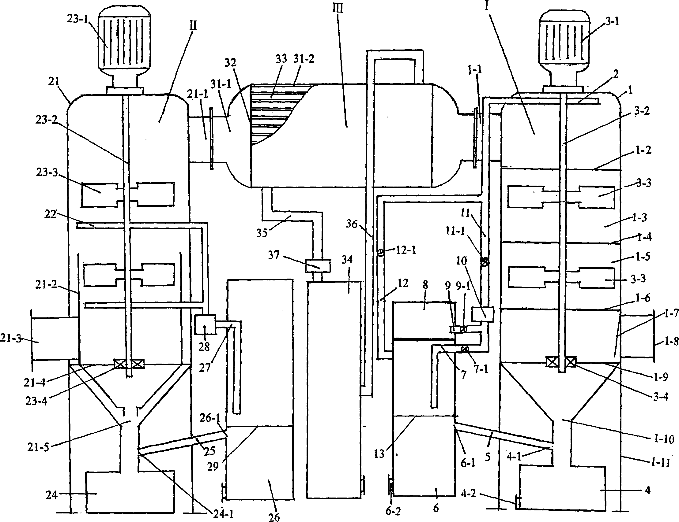
[0023]Example 2 has a spray centrifugal scrubber II, a foam cleaner I and a cooler III, and the foam cleaner I is the same as Example 1. The scrubber is fixed by the support frame. The inlet and outlet ports 21-3 and 21-1 of the scrubber are respectively arranged on the lower and upper parts of the cylinder body 21. The lower part of the cylinder body 21 has an inner cylinder 21-2 and a slag outlet. 21-5 is arranged at the bottom of the cylinder 21, the slag outlet 21-5 is connected to the slag collecting box 24, the dust removal cylinder 21 is provided with a sprayer 22 and a rotating shaft 23-2, the nozzle of the sprayer 22 is upward, and the rotating shaft 23-2 is connected with the place. The main shaft of the motor 23-1 on the top of the cylinder body 21 is connected, and the end of the rotating shaft 23-2 is connected with a bearing 23-4, which is installed in the bearing support 21-4 connected with the dust removal cylinder 21-1. The rotating shaft 23-2 is connected wit...


PUM


Abstract

The invention is a kind of dust catching and smoke clarifying device which uses clarifier to form foam layer. It has foam clarifier, there's sprayer, upper and nether net board in the barrel. The foam room is between the two boards. The smoke inlet and outlet of foam clarifier are set on the upper and nether part. The dust outlet is set on the bottom of the barrel and connects with dust gatheringbox. There's an axis in the barrel which connects with the axis of the electromotor. The axis in the foam room connects some vanes; there's circular water box and clarifier box by the side of the barrel.

Description

technical field [0001] The present invention relates to a flue gas purification device. Background technique [0002] At present, there are many ways to control smoke and dust, each with different characteristics. Among them, wet dust removal is a more common treatment method. Wet dust removal is to wash dust-containing gas with water, and use the formed liquid film, droplets or bubbles to capture the dust in the gas. The particles and dust particles are discharged with the water, and the gas is purified. The liquid film, droplets or bubbles mainly achieve the purpose of capturing the dust particles in the exhaust gas through inertial collision, the diffusion of fine dust particles, the condensation effect of the liquid film and droplets after humidifying the dust particles and the adhesion to the dust particles. . The bath-type dust collectors in the wet dust collector include water bath dust collectors, foam dust collectors, impulse dust collectors and other forms. Their...

Claims


Application Information

Patent Timeline
IPC IPC(8): B01D47/00B01D53/78
Inventor 杨长明
Owner 杨长明
Why Eureka
Try Eureka