Oil-pressure control device of automatic speed variator

A technology of automatic transmission and oil pressure control, which is applied in the direction of transmission control, components with teeth, belts/chains/gears, etc., to prevent sudden loss of torque and promote the effect of increasing oil viscosity

Inactive Publication Date: 2004-01-28
AISIN AW CO LTD +1
View PDF0 Cites 9 Cited by
  • Summary
  • Abstract
  • Description
  • Claims
  • Application Information

AI Technical Summary

Problems solved by technology

Therefore, in the so-called D-N control, the oil discharged from the hydraulic servo is rapidly discharged from the control valve through the manual valve. At this time, a shock may occur due to a sudden loss of torque of the frictional engagement parts.

Method used


Image

  • Oil-pressure control device of automatic speed variator
  • Oil-pressure control device of automatic speed variator
  • Oil-pressure control device of automatic speed variator

Examples


Embodiment Construction

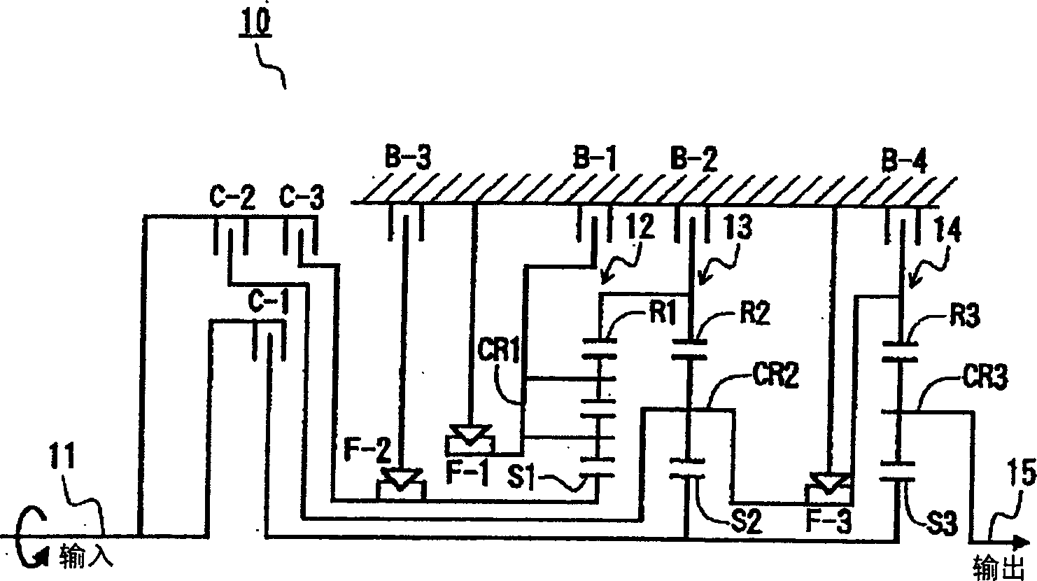
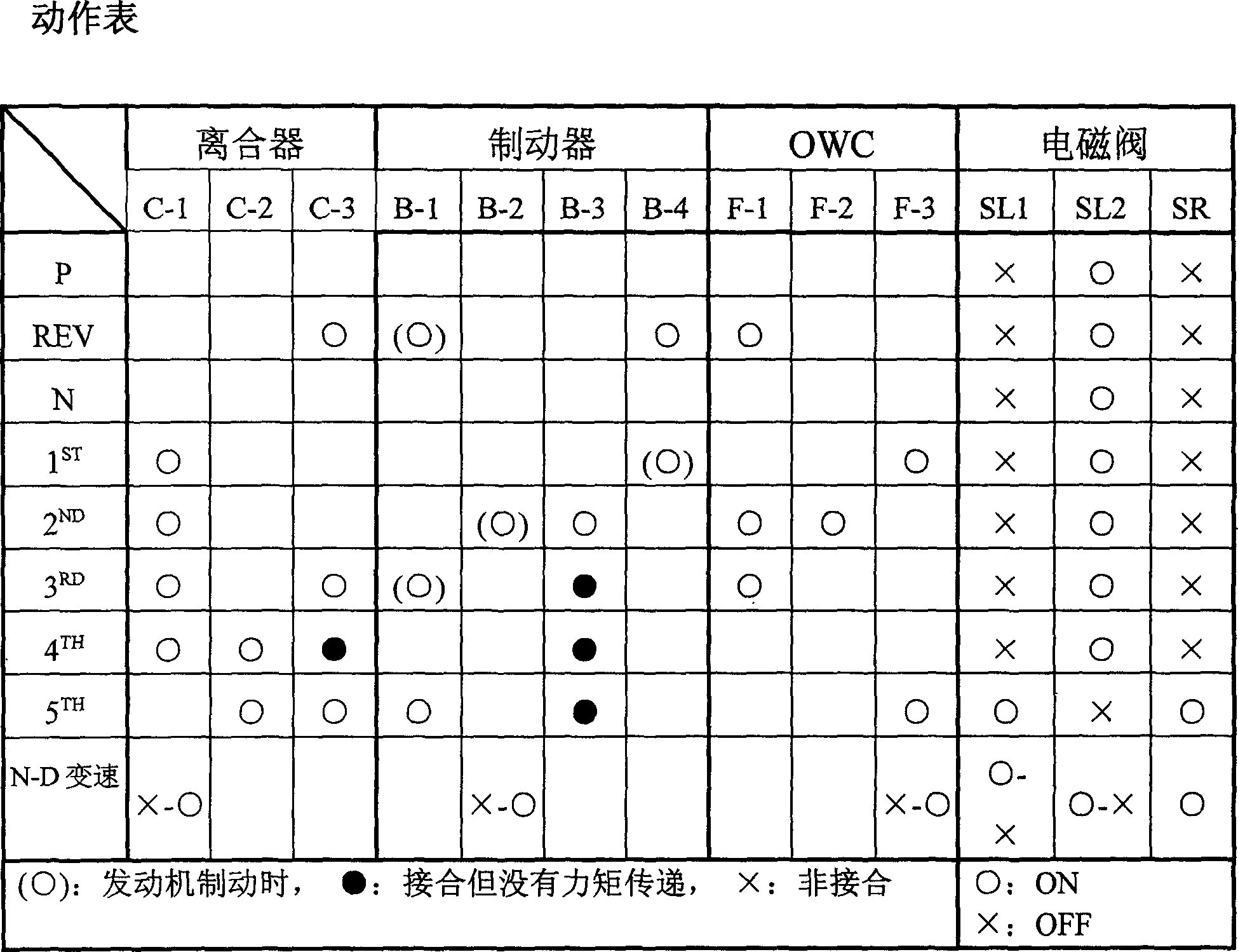
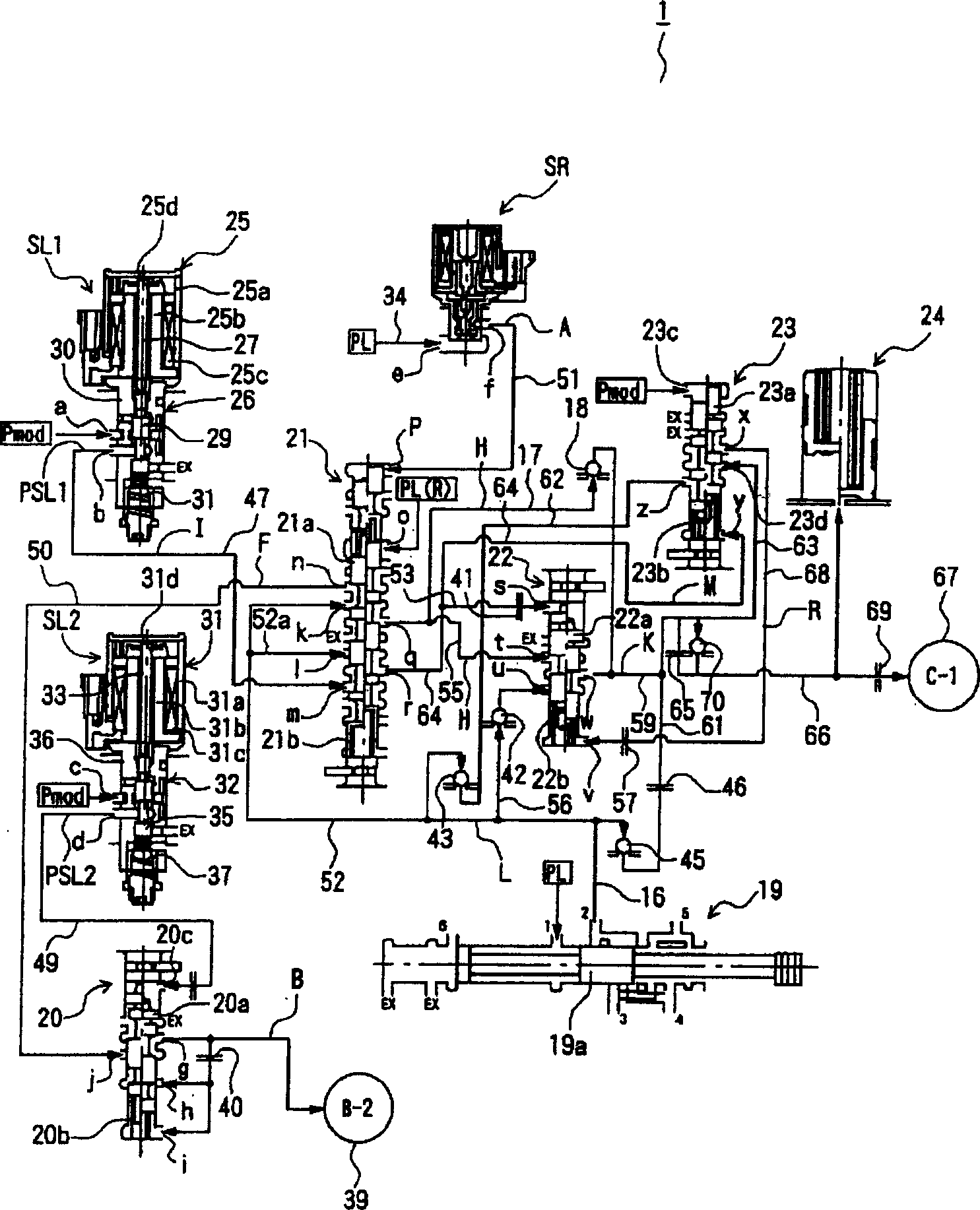
[0025] Embodiments of the present invention are described below with reference to the drawings. figure 1 is a schematic diagram showing an automatic transmission mechanism to which the present invention is applied, figure 2 is an operation table showing the engagement state of the frictional engagement elements in each gear, image 3 It is a schematic diagram showing the hydraulic control device of the present invention.

[0026] For example, in an automatic transmission disposed in a vehicle or the like, the oil pressure control device 1 of the present invention is included, and the oil pressure control by the oil pressure control device 1 is performed by controlling a plurality of friction engagement members (for example, clutches C-1 to C-1). -3. The engagement state of the brakes B-1 to B-4) is controlled to form, for example, an automatic transmission mechanism (gear mechanism) 10 with 5 forward speeds and 1 reverse speed.

[0027] Such as figure 1 As shown, the above...


PUM


Abstract

The invention provides an oil pressure control device for an automatic speed-changer (1), wherein, when a clutch (C-1) is released, a bonder pressure (K), which is supplied by an oil type servo-motor (67) used for the clutch (C-1), can bypass a control valve (22) and be exhausted through an circuitous oil circuit (61, 62, and 63). Moreover, the exhaust is forbidden to use the ball check valve (42), which can safely prevent the oil from being exhausted through the path between a manual valve (19) and an input port (u). Therefore, the oil pressure control device has the advantage of avoiding that the valve, especially the middle part, of the control valve be stuck.

Description

technical field [0001] The present invention relates to an oil pressure control device of an automatic transmission installed in an automobile, and in particular relates to an oil pressure control device of an automatic transmission capable of preventing the valve from being stuck in a control valve for supplying engagement pressure to a friction engagement member. Background technique [0002] In the prior art, there is known the oil pressure of an automatic transmission that includes a plurality of shift valves and control valves connected to each other to form a predetermined circuit, selects and switches these valves, and switches gears in a timely manner according to the operation of the shift lever. Control device (hereinafter also referred to as "oil pressure control device"). In such a hydraulic control device, control is performed by supplying a predetermined gear pressure such as D (drive) gear pressure from a control valve through a hydraulic servo for a so-called...

Claims


Application Information

Patent Timeline
Patent Type & Authority Applications(China)
IPC IPC(8): F16H61/00F16H61/02F16H61/06
CPCF16H61/0206F16H61/067F16H2061/1204
Inventor 藤峰卓也深津彰野田和幸安藤雅彦野崎和俊金田俊树柏原裕司
Owner AISIN AW CO LTD
Why Eureka
Try Eureka