Gas flow sensor

A gas flow and sensor technology, applied in the direction of liquid/fluid solid measurement, measurement flow/mass flow, instruments, etc., can solve the problems of complex structure, poor measurement accuracy, low sensitivity, etc., and achieve high measurement accuracy, fast response speed, The effect of high sensitivity

Inactive Publication Date: 2004-01-28
刘冬
View PDF2 Cites 2 Cited by
  • Summary
  • Abstract
  • Description
  • Claims
  • Application Information

AI Technical Summary

Problems solved by technology

The displacement gas flow sensor described in this patent also has the disadvantages of complex structure, low sensitivity and poor measurement accuracy.

Method used


Image

  • Gas flow sensor
  • Gas flow sensor
  • Gas flow sensor

Examples


Embodiment Construction

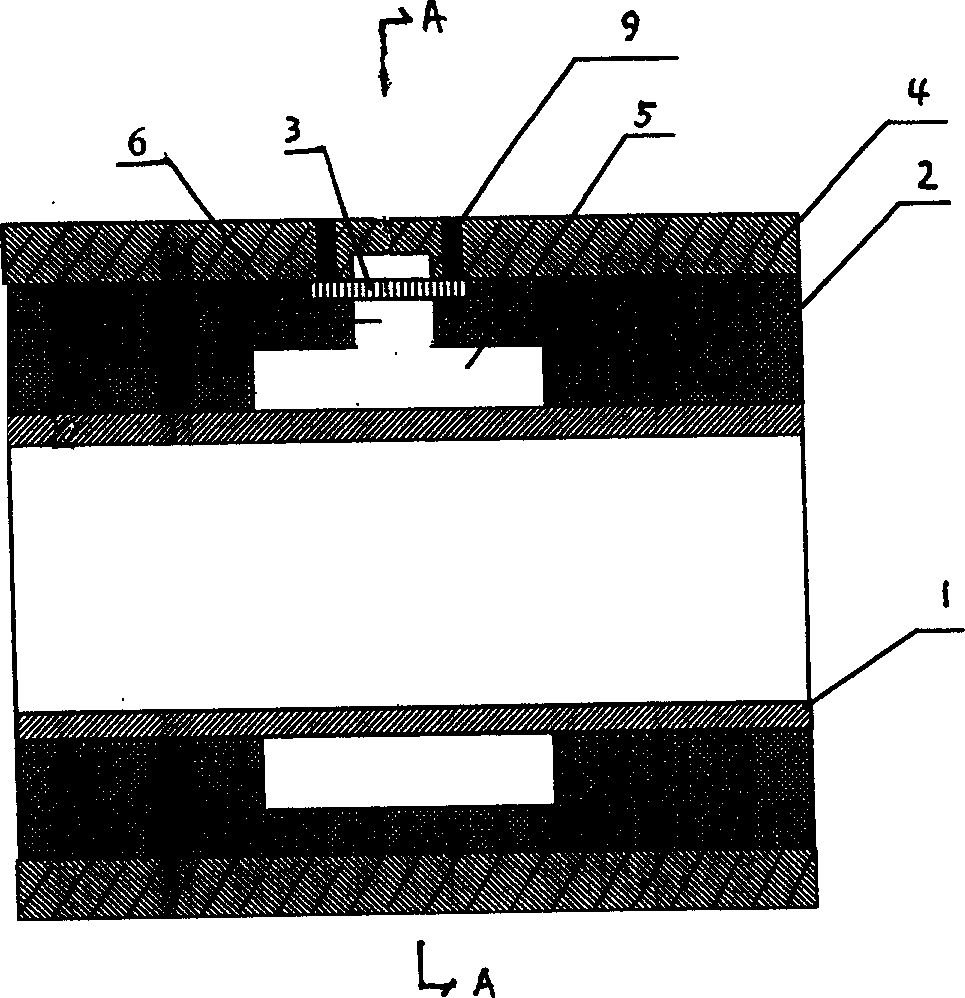
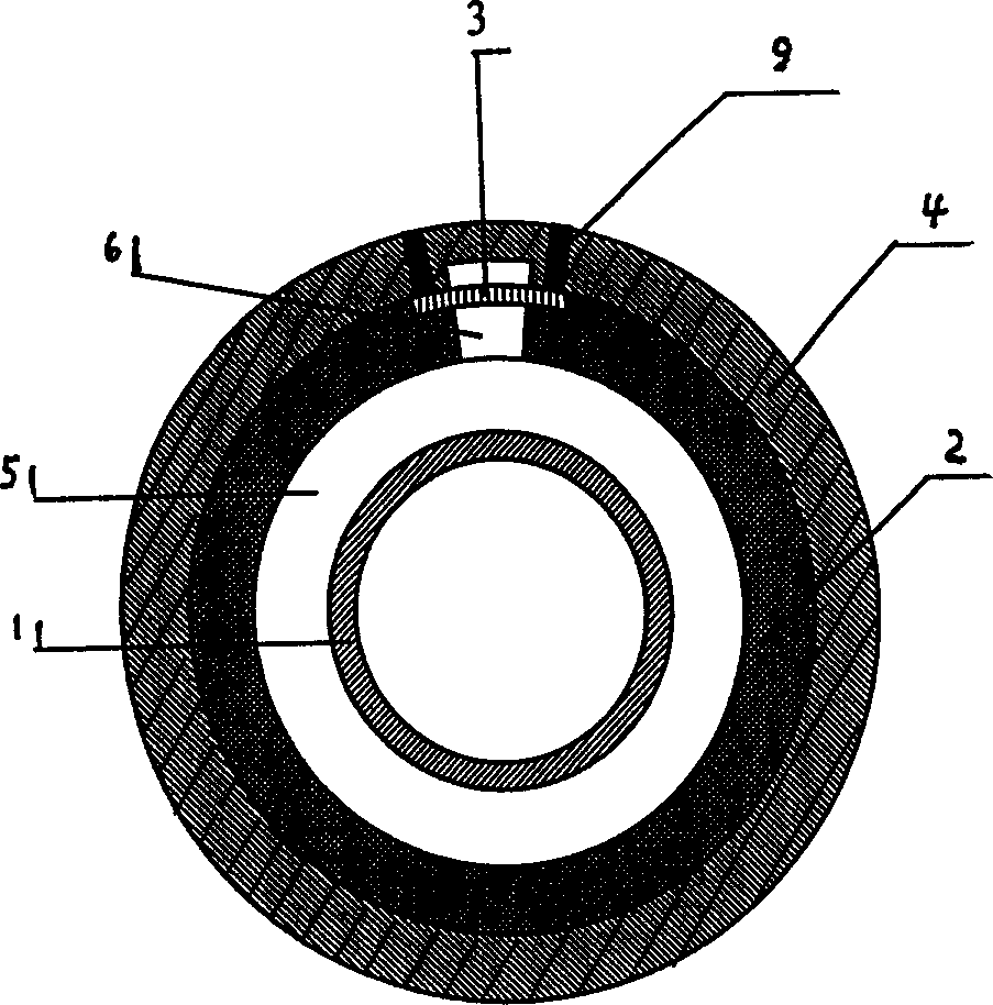
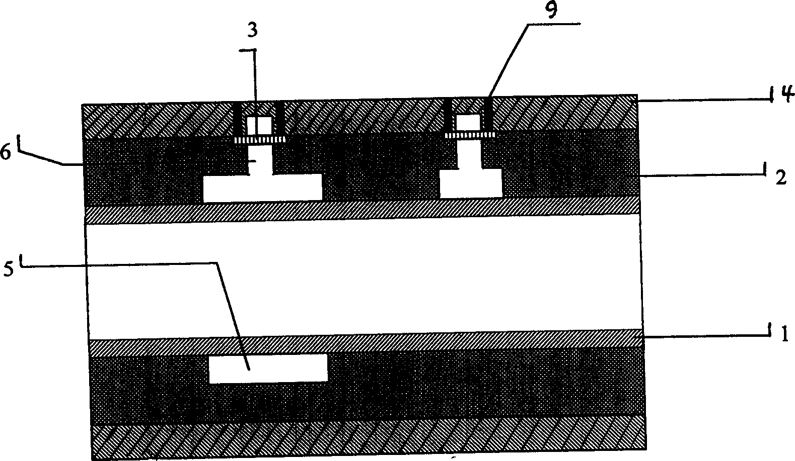
[0021] Referring to the accompanying drawings, the gas flow sensor of the present invention includes a tubular plastic shell 4, a tubular plastic inner shell 2 is inserted in the inner cavity of the outer shell 4, and a tubular plastic inner shell 2 is inserted in the inner cavity of the inner shell 2. A tubular metal inner membrane 1, the inner shell 2 is provided with 1-3 vibration cavities 5 and vibration transmission channels 6 respectively connected to each vibration cavity 5, wherein each vibration cavity 5 is along the inner circular surface of the inner shell 2 Setting, the inner casing 2 is equipped with induction diaphragms 3 that respectively block each vibration transmission channel 6, and each induction diaphragm 3 is connected with a metal post 9, and the vibration chamber 5 can be annular, semi-annular or arc-shaped , the sensing diaphragm 3 includes a varistor diaphragm, a piezoelectric diaphragm and a capacitive diaphragm, and other types of sensing diaphragms ...


PUM


Abstract

The sensor comprises the tubular case and inner hull inside the case, the tubular inner membrane and the passage for transferring vibration. The said passage is connected to the vibration cavity setup at inner circle surface of the inner hull. An induction membrane installed on the inner hull can block out the passage. Metal pole is connected to the induction membrane. The sensor possesses the features of simple structure, low cost, small pressure loss of measured gas and high accuracy in measurement.

Description

technical field [0001] The invention relates to a gas flow sensor. Background technique [0002] A gas flow meter is a device for measuring gas flow, and its key component is a sensor. General-purpose gas flowmeters can basically be divided into four types: vane type, Karman vortex type, hot wire type and hot film type. These four types of gas flowmeter sensors have the common disadvantages of complex structure, high cost, large pressure loss, low sensitivity and poor measurement accuracy. For example, the patent No. is 92204506.2 gas flowmeter, in the disclosed technical solution, the sensor part includes an impeller driven by the flowing gas to rotate in the gas channel and with large and small blades, and the impeller is fixed with permanent magnet steel An electromagnetic sensor is fixed on the circumference corresponding to the impeller. When the flowing gas pushes the impeller to rotate, the permanent magnet steel body fixed on the impeller also rotates accordingly. ...

Claims


Application Information

Patent Timeline
Patent Type & Authority Applications(China)
IPC IPC(8): G01F3/22
Inventor 刘冬
Owner 刘冬
Why Eureka
Try Eureka