

Semi transmission liquid crystal display device
A liquid crystal display device, semi-transmissive technology, applied in nonlinear optics, instruments, optics, etc., can solve problems such as designing device structure and processing signals, and achieve the effects of increasing stability, increasing aperture ratio, and improving reliability
- Summary
- Abstract
- Description
- Claims
- Application Information
AI Technical Summary
Problems solved by technology
Method used
Image

Examples
no. 1 example
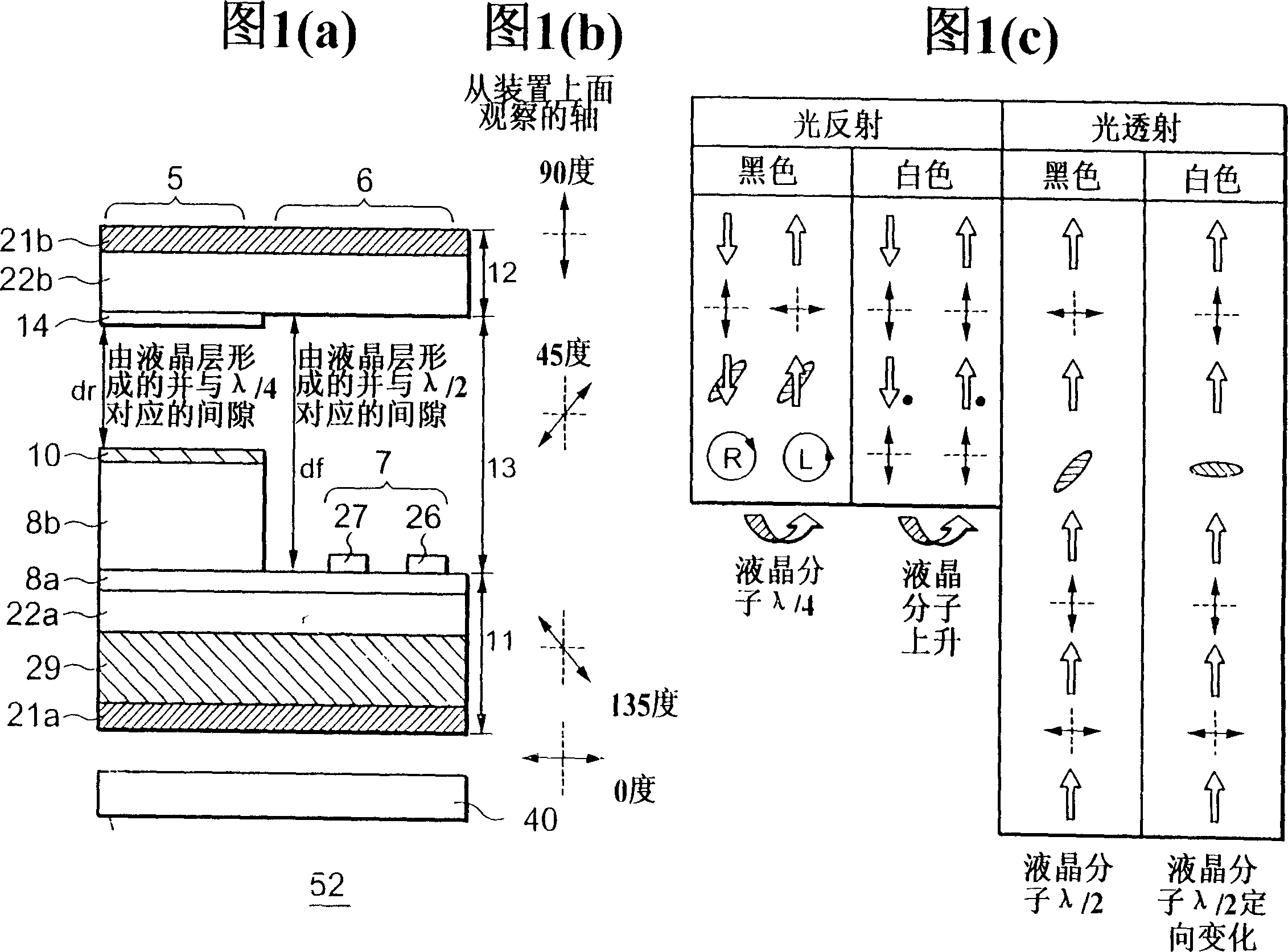
[0074] The transflective liquid crystal display device according to the first embodiment of the present invention has: a reflective region, wherein the liquid crystal molecules are driven by a vertical electric field; and a transmissive region, wherein the liquid crystal molecules are driven by a horizontal electric field. 1( a ) is a cross-sectional view showing how to optically arrange the components constituting the unit of the transflective liquid crystal display device 52 of the first embodiment, and FIG. 1( b ) shows the During this device, polarizers 21a, 21b, liquid crystal layer 13, and one-half wavelength (λ / 2) plate 29 are oriented to each other at an alignment angle, and Fig. 1 (c) shows how these components work in the reflective region and operate in the transmissive region.
[0075] As shown in Figure 1 (a), the transflective liquid crystal display device 52 includes: a lower substrate 11; an opposite substrate 12; a liquid crystal layer 13, which is sandwiched ...
no. 2 example
[0081] In the transflective liquid crystal display device according to the second embodiment of the present invention, the liquid crystal molecules are driven by a horizontal electric field in the reflective region and the transmissive region. 4( a ) is a cross-sectional view showing how to optically arrange the cells of the semi-transmissive liquid crystal display device 53 of the second embodiment, and FIG. 4( b ) shows when the device is viewed from the opposite substrate 12 side , the alignment angles at which the polarizers 21a, 21b, the liquid crystal layer 13 and the half-wave plate 29 are oriented to each other, and FIG. 4(c) shows how these components operate in the reflective and transmissive regions.
[0082] As shown in Figure 4 (a), since the semi-transmissive liquid crystal display device 53 of the second embodiment has the same cross-sectional structure as that shown in Figure 20 (a), except that the device 53 has a half-wavelength plate 29, Therefore, the descr...
no. 3 example
[0085] Although in the first and second embodiments, only how the liquid crystal display device is configured to optically arrange components and how to operate has been described, in the third embodiment, reference will be made to Figure 5 Turning to FIG. 10, how to establish the layered structure and electrode constitution employed in the second embodiment will be explained. Figure 5 is a plan view of the liquid crystal display device 54 of the third embodiment, Figure 6 is a plan view of an interconnection level formed with electrodes 7 provided in the transmissive region and provided for generating a horizontal electric field, Figure 7 is a plan view of the interconnection level formed with the electrode 7 provided in the reflective area and provided for generating a horizontal electric field. Figure 8(a) is along the Figure 5 The cross-sectional view taken along the line I-I, and Fig. 8(b) is along the Figure 5 A cross-sectional view taken on line IV-IV. Figure ...
PUM
 Abstract
Description
Claims
Application Information