
Method for implementing quick optical fibre protective inversion in ring network and its equipment

A fiber protection and fast technology, applied in the field of computer communication, can solve the problems of cumbersome and unsatisfactory uploading of fiber break alarms on the standby board, and achieve the effects of shortening the switching time of fiber protection, low cost, and avoiding frequent scheduling

Inactive Publication Date: 2004-02-25
HUAWEI TECH CO LTD
View PDF0 Cites 17 Cited by
  • Summary
  • Abstract
  • Description
  • Claims
  • Application Information

AI Technical Summary

Problems solved by technology

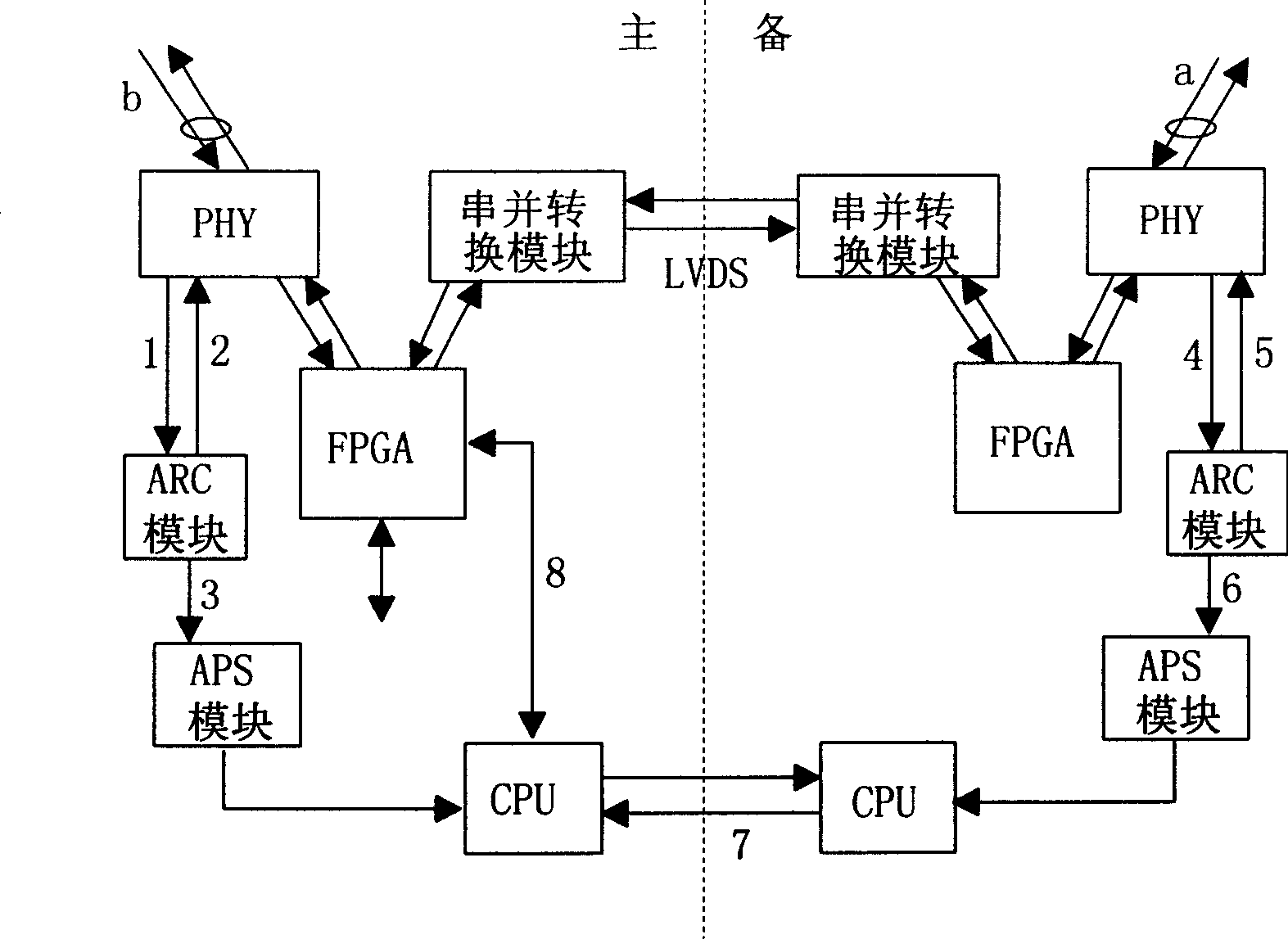
[0005] It can be seen from the above existing technologies that it is easy to respond to the fiber-cut alarm of the main board in a timely manner, while the fiber-cut alarm of the standby board can only be interrupted by the interface chip through the single-board software of the standby board. The channel notifies the mainboard host, and then the host software issues commands to perform the switching operation. Due to the delay of multiple software scheduling in this process, the switching time is often hundreds of milliseconds, or even reaches the microsecond level, and the standby board fiber cut alarm Uploading is too cumbersome and often fails to meet the requirements of the Bellcore GR-2837 standard that the protection switching time should not exceed 50 milliseconds

Method used


Image

  • Method for implementing quick optical fibre protective inversion in ring network and its equipment
  • Method for implementing quick optical fibre protective inversion in ring network and its equipment
  • Method for implementing quick optical fibre protective inversion in ring network and its equipment

Examples


Embodiment Construction

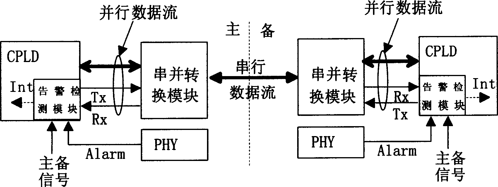
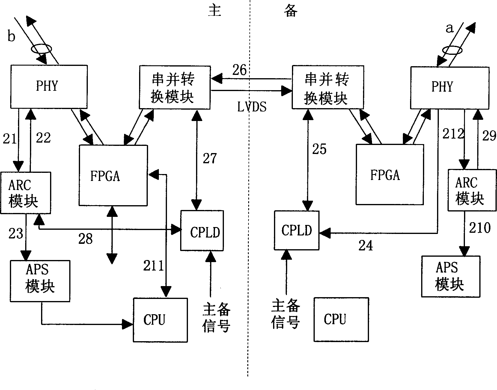
[0034] The core of the present invention is to transmit the interruption of the PHY chip caused by the fiber breakage of the backup device (that is, the standby board) to the main device (that is, the main board) through the underlying hardware, instead of using the main and standby links to send light from the APS module of the standby board to the main board. The interface fault message utilizes the characteristics of fast response of the hardware gate circuit, thereby avoiding complicated software processing, greatly shortening the protection switching time, and ensuring the security of the loop service.

[0035] The realization of the present invention is to increase the alarm detection module in the existing main and standby board CPLD (Complex Programable Logic Device, complex programmable logic device), and this module is used for completing the transmission of the alarm information of the PHY layer chip of the standby board to the main board, and the inter-board The sig...


PUM


Abstract

The present invention relates to a method for implementing fast optical fibre protection replacement in the ring network and its equipment. The method mainly includes the folling steps: firstly, notifying the fibre-breaking warning message produced by standby equipment to main equipment by means of bottom layer hardware, then according to the received fibre-breaking warning message making opticalfibre protection replacement by main equipment. In the complex programmable logic device of main equipment and standby equipment the warning detection module, standby equipment serial-parallel conversion module and main equipment serial-parallel conversion module are set respectively.

Description

technical field [0001] The invention relates to the technical field of computer communication, in particular to a method and device for realizing fast optical fiber protection switching in a ring network. Background technique [0002] In the ATM VPRing (ATM Virtual Path Ring, asynchronous transfer mode virtual channel ring) ring network solution, the ring network service is accessed by the optical port of the main control board on the node. LVDS (Low Voltage Differential Signal) technology is used to transmit high-speed services between the active and standby boards. After the loop service is accessed by the working router, it is logically judged whether it is a local service. If it is a local service, it will be processed by the local node; if it is not a local service, it will be forwarded by the logic and transparently transmitted to the opposite board through the LVDS link, and the logic of the opposite board will also be transparently transmitted. Processing, so that t...

Claims


Application Information

Patent Timeline
Patent Type & Authority Applications(China)
IPC IPC(8): H04B1/74H04B10/032
Inventor 余忠洋
Owner HUAWEI TECH CO LTD
Learn More