Cylindrical washer
A drum-type washing machine and drum technology are applied to other washing machines, washing machines with containers, control devices of washing machines, etc., and can solve the problems of uneven washing, prolonging washing time, reducing washing power, etc.
- Summary
- Abstract
- Description
- Claims
- Application Information
AI Technical Summary
Problems solved by technology
Method used
Image
Examples
Embodiment 1
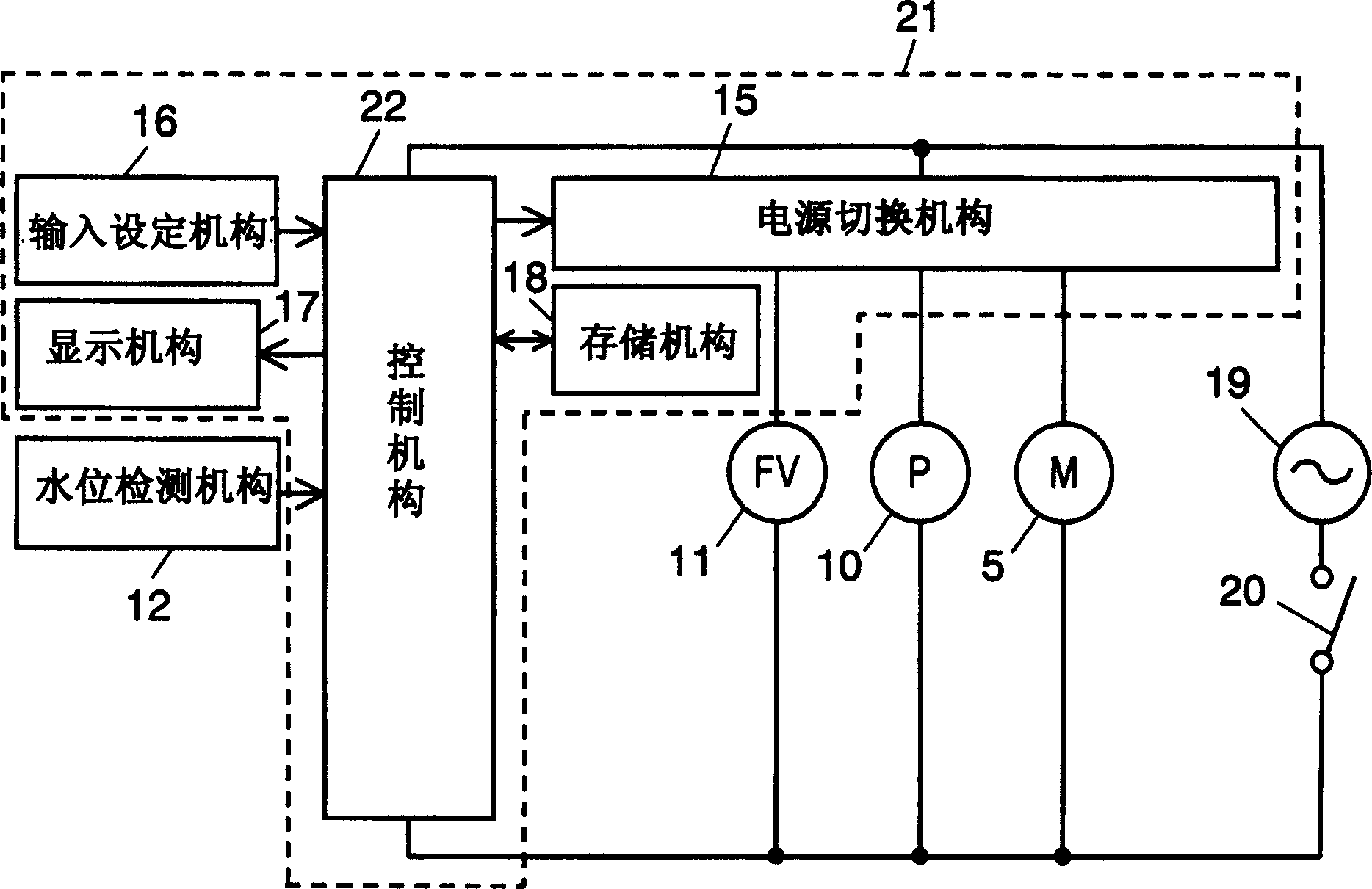
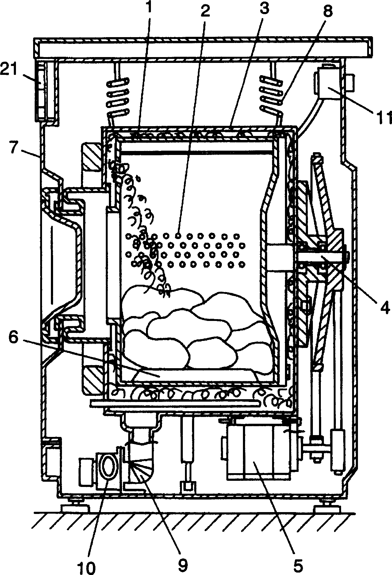
[0023] figure 1 It is a block circuit diagram of a drum type washing machine in an embodiment of the present invention. figure 2 It is a cross-sectional view of the front-loading washing machine according to Embodiment 1 of the present invention. figure 2 The left side of the screen indicates the front of the washing machine, and the right side indicates the rear side of the washing machine.
[0024] exist figure 1 and figure 2 Among them, the control device 21 has a control mechanism 22 composed of a microcomputer, and controls the actions of the motor 5, the drain pump 10, the water supply valve (water supply mechanism) 11, etc. by means of the power switching mechanism 15. As a result, a series of steps such as washing, rinsing, and dehydration are sequentially controlled. During the washing process, the washing liquid foam generated by the control mechanism 22 is added to the laundry in the rotary drum 1 for washing.
[0025] Next, the operation of the washing pr...
Embodiment 2
[0033] Image 6 It is a sectional view of the front-loading-type washing machine in Example 2 of the present invention. Image 6 The left side of the screen is the front of the washing machine, and the right side is the rear side of the washing machine.
[0034] as in Image 6 As shown above, in the drum type washing machine of Embodiment 2, the central axis of rotation of the rotating shaft 4 of the rotating drum 1 is inclined, and the front of the rotating drum is higher than the rear. The other structures are the same as in Embodiment 1, and are assigned the same symbols, and descriptions thereof are omitted.
[0035] During the washing process, the detergent foam generated by the control mechanism 22 of the control device 21 soaks into the laundry in the rotary drum 1 to perform washing. At this time, the detergent foam flows from the position where the central axis of rotation is high (in front of the rotating drum) to the oblique rear.
[0036] Next, the washing oper...
Embodiment 3
[0042] In this embodiment, when the control mechanism 22 generates detergent foam and provides detergent foam during the washing process, the rotary drum 1 is rotated. Other structures are the same as the above-mentioned embodiment 1.
[0043] The operation of the washing process in the above construction will now be described. Detergent foam was generated in the same manner as in Example 1. The detergent foam produced by the continuous rotation of the rotary drum 1 rises from between the rotary drum 1 and the water receiving tank 3 under the action of centrifugal force, and overflows from the front upper part of the washing machine. At this time, the detergent foam is supplied while rotating the rotary drum 1, and the detergent foam generally soaks the laundry in the rotary drum 1, and then returns to between the rotary drum 1 and the water receiving tank 3 through the laundry. This allows the detergent suds to circulate.
[0044] As described above, by supplying detergent...
PUM
 Abstract
Description
Claims
Application Information
 - R&D
- Intellectual Property
- Life Sciences
- Materials
- Tech Scout
- Unparalleled Data Quality
- Higher Quality Content
- 60% Fewer Hallucinations
Browse by: Latest US Patents, China's latest patents, Technical Efficacy Thesaurus, Application Domain, Technology Topic, Popular Technical Reports.
© 2025 PatSnap. All rights reserved.Legal|Privacy policy|Modern Slavery Act Transparency Statement|Sitemap|About US| Contact US: help@patsnap.com


