Inputting overvoltage protection circuit and electric device with the protection circuit

A technology for protecting circuits and overvoltage, which is applied in emergency protection circuit devices, protection for overvoltage responses, circuit devices, etc., and can solve problems such as unreliable circuit cutoff, poor reactivity, and poor circuit reliability.

Inactive Publication Date: 2004-03-03
TOHOKU RICOH CO LTD
View PDF1 Cites 17 Cited by
  • Summary
  • Abstract
  • Description
  • Claims
  • Application Information

AI Technical Summary

Problems solved by technology

[0039] However, the disadvantages of Zener diodes and silicon varistors are that there are not many high withstand voltage components and the reactivity is poor.
Avalanche diodes may be damaged in the short-circuit mode (connection mode) or in the open mode (open mode). Since they cannot function as an overvoltage protection element when damaged in the open mo

Method used


Image

  • Inputting overvoltage protection circuit and electric device with the protection circuit
  • Inputting overvoltage protection circuit and electric device with the protection circuit
  • Inputting overvoltage protection circuit and electric device with the protection circuit

Examples


Embodiment approach 1

[0072] (implementation mode 1: Figure 1 ~ Figure 3 )

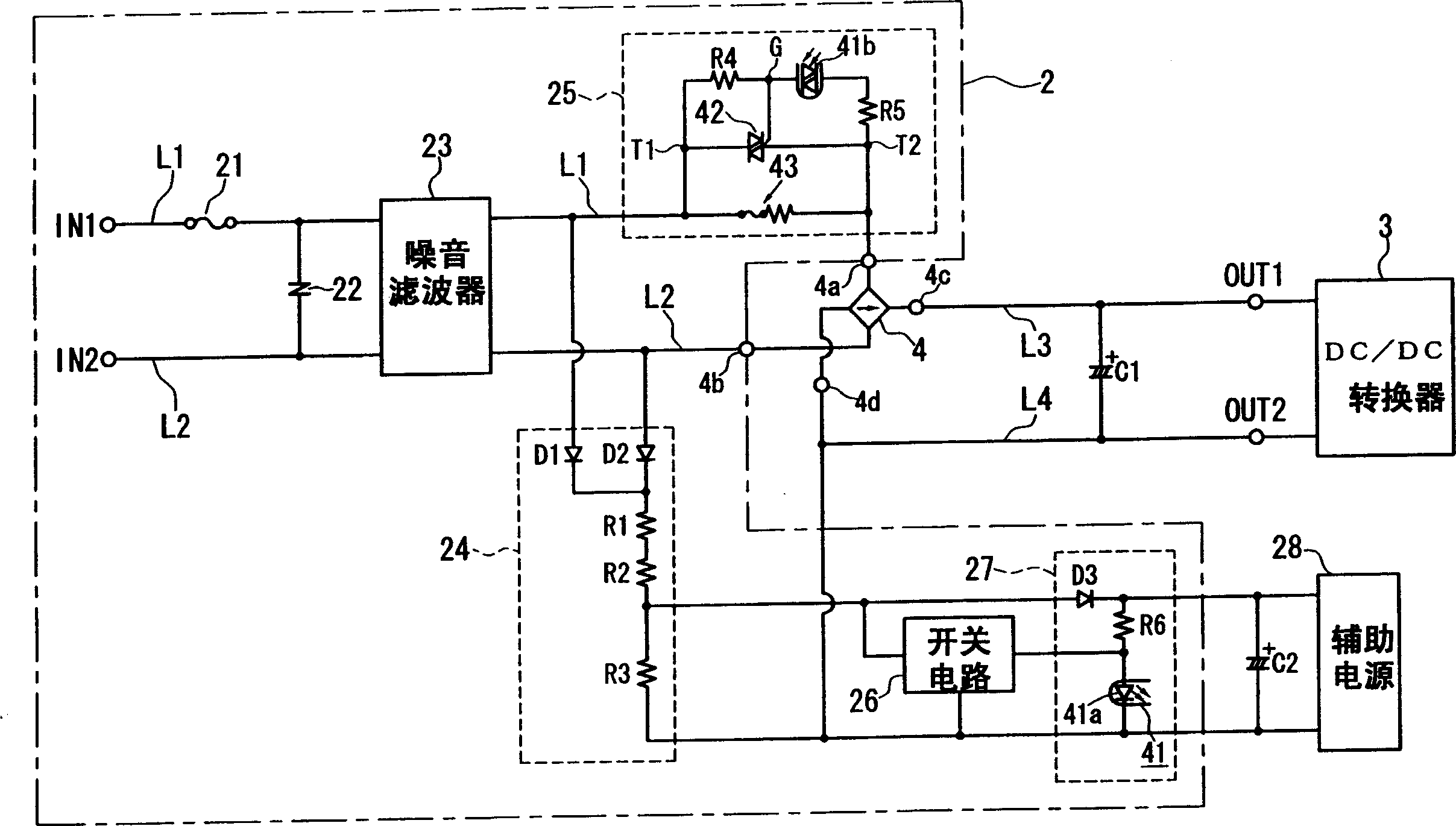
[0073] figure 1 It is a circuit diagram of a power supply circuit for a DC / DC converter provided with an input overvoltage protection circuit according to Embodiment 1 of the present invention.

[0074] The power supply circuit is compatible with the following point Figure 20 The conventional example described is the same: it has two power lines AC lines L1 and L2 having two AC input terminals IN1 and IN2 connected to an AC power source by inserting a power plug into a commercial AC power outlet. Hereinafter, when describing the power supply circuit, for simplicity, the side close to the AC input terminals IN1, IN2 of the AC lines L1, L2 is called "input side", and the opposite side (the side close to the diode bridge 4 as a load) is called "input side". for the "output side". The part 2 surrounded by a dotted line is an AC part that transmits an alternating current, and the part outside it is a DC or DC / AC part that...

Embodiment approach 2

[0134] (implementation mode 2: Figure 5 )

[0135] Next, Embodiment 2 of the present invention will be described. Figure 5 The power supply circuit provided with the input overvoltage protection circuit is shown together with the switching regulator as the load circuit, and figure 2 Same circuit. This embodiment is different from the above Figure 4 Most of the illustrated Embodiment 1 is common, and the same symbols are attached to the common parts, and the description thereof will be omitted. exist Figure 5 , omitted to indicate Figure 4 The dot-dash line illustration of the 3 parts of the DC / DC converter shown.

[0136] in the Figure 5 The embodiment shown is the same as Figure 4 The difference of the illustrated embodiment is that a four-coil transformer 31 with a drive coil 31d added is used instead of the DC / DC converter transformer 31, and the inrush current prevention circuit 55 and the transmission circuit 57 are connected to the Figure 4 While the in...

Embodiment approach 3

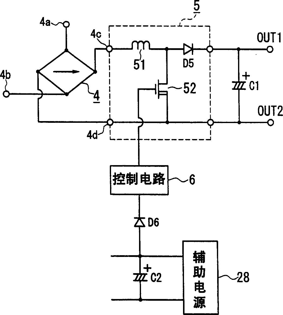
[0154] (implementation mode 3: Image 6 )

[0155] Next, Embodiment 3 of the present invention will be described. Image 6 A power supply circuit equipped with an input overvoltage protection circuit is shown together with a switching regulator as a load device, and Figure 4 with Figure 5 Same circuit diagram. This embodiment is largely the same as the above Figure 5 Embodiment 2 shown is common, and the same symbols are attached to the common parts, and description thereof will be omitted. that is Image 6 Also omitted in Figure 4 An illustration of dotted lines representing parts of the DC / DC converter 3 is shown.

[0156] in the Image 6 The embodiment shown is the same as Figure 5 The difference of the illustrated embodiment is that the detection circuit 54, the switch circuit 56 and the transmission circuit 67 are respectively connected with Figure 5 The detection circuit 24, the switch circuit 26 and the transmission circuit 57 are different, and the star...


PUM


Abstract

To surely cut off a circuit without relying on the performance or reliability of an overvoltage protection element if an input overvoltage is generated in a power supply line. An inrush current prevention circuit 25 is interposed in at least one of AC line L1 and L2, and a detection circuit 24 detects voltages of the AC lines L1 and L2. If a detected voltage exceeds a prescribed value, a switch circuit 26 is turned on to transmit the excess to the inrush current prevention circuit 25 by a phototriac coupler 41 of a transmission circuit 27. In the inrush current prevention circuit 25, a resistor 43 with a temperature fuse and a triac 42 which is a semiconductor switch element are connected in parallel. The triac 42 is normally conductive, and when information that the switch circuit 26 is turned on is transmitted by the transmission circuit 27, it is opened. It makes a current to flow the resistor 43 with temperature fuse, and a power feeding circuit is disconnected when the temperature fuse is blown off.

Description

technical field [0001] The present invention relates to an input overvoltage protection circuit arranged on a power supply circuit that supplies power to a load device or a load circuit from an AC power source, and is used to cut off the power supply circuit when an external surge or an input overvoltage occurs, and to prevent damage to the load device or the load circuit And a switching regulator including the input overvoltage protection circuit in the power supply circuit, etc. Background technique [0002] Conventionally, switching regulators, DC load devices using the switching regulators, AC load devices such as heaters, inverters, and other load devices or load circuits powered from commercial frequency AC power sources (these are called electrical device). Moreover, a protection circuit is usually provided on the AC power supply circuit to protect these electrical devices from input overvoltage caused by external surges and the like. [0003] The so-called external...

Claims


Application Information

Patent Timeline
IPC IPC(8): H02H3/10H02H3/08H02H3/20H02H7/125H02M3/28
Inventor 镰田久浩
Owner TOHOKU RICOH CO LTD
Why Eureka
Try Eureka