High temperature thermal cutoff device

A warm, fusing technology, used in circuit devices, automatic disconnection emergency protection devices, emergency protection devices, etc.

Inactive Publication Date: 2010-03-31
THERM O DISC
View PDF6 Cites 14 Cited by
  • Summary
  • Abstract
  • Description
  • Claims
  • Application Information

AI Technical Summary

Problems solved by technology

TCOs are usually designed to cut off curre

Method used


Image

  • High temperature thermal cutoff device
  • High temperature thermal cutoff device
  • High temperature thermal cutoff device

Examples


Embodiment 1

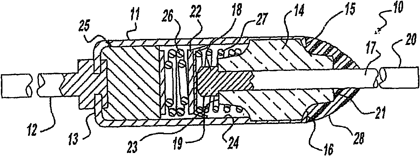
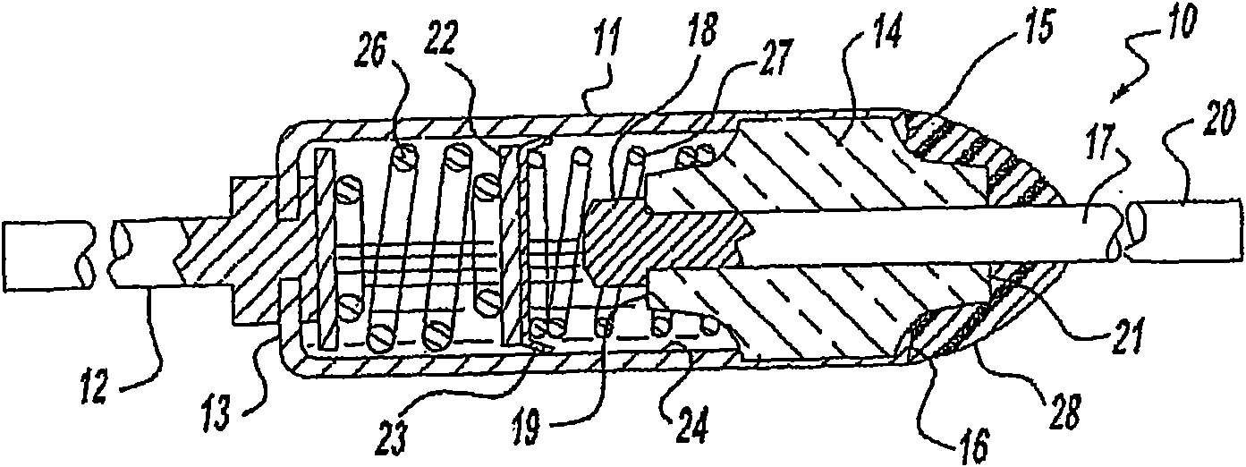
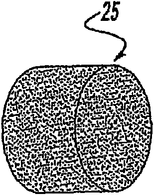
[0076] According to various aspects of the invention, a high temperature TCO device is formed as follows. Thermal pellets are formed by combining 980 g to 1000 g of triptycene (commercially available from Sigma-Aldrich manufacturer, 95-99% pure) with 20 g to 0.5 g of colorant, binder and / or mold release agent mix. The homogenized mixture was processed on a standard powder compaction press (commonly available from pharmaceutical equipment suppliers). Powder is fed through a gated powder flow control system and evenly distributed over the rotating die table. The mold is filled with the powder and the powder in the mold is punched under a pressure of about 1 to 4 tons to form compacted powder pellets having a density of 29 to 50 pellets / gram. The thermal pellets were placed into a highly conductive metal closed-end cylinder with an inner diameter close to the outer diameter of the TCO thermal pellets. The closed end of the barrel is staked shut with axial conductive metal lead...


PUM

PropertyMeasurementUnit
Transition temperatureaaaaaaaaaa

Abstract

The present disclosure provides high temperature thermal cutoff devices having a high-temperature thermal pellet with a transition temperature of greater than or equal to about 240 DEG C and comprising at least one organic compound. The pellet is disposed in a housing, which is sealed with a high-temperature seal that provides substantial sealing up to at least the transition temperature. The high-temperature TCO also has a current interruption assembly, which establishes electrical continuity in a first operating condition corresponding to an operating temperature of less than said transitiontemperature and discontinues electrical continuity when the operating temperature exceeds the transition temperature. Methods of making such high-temperature thermal cut off devices are also provided.

Description

[0001] Cross References to Related Applications [0001] This application claims the benefit of priority to US Provisional Application No. 61 / 086,330, filed August 5, 2008. The entire disclosure of the above application is incorporated herein by reference. technical field [0002] The present invention relates to electrical current interruption devices and, more particularly, to high temperature current interruption safety devices or thermal cut-offs that provide protection against overheating conditions. Background technique [0003] The statements in this section merely provide background information related to the present invention and may not constitute prior art. [0004] Appliances, electronics, motors, and other electrical devices generally have optimum ranges for operating temperatures. The temperature range over which damage to system components may occur or where the device may become a potential safety hazard in the appliance or to the end user plays an importan...

Claims


Application Information

Patent Timeline
IPC IPC(8): H01H85/04H01H85/06H01H69/02
CPCH01H2037/762H01H85/055H01H37/765H01H69/02H01H85/04H01H85/06H01B1/12Y10T29/49105Y10T29/49107H01H2037/768H01H2223/008H01H2235/004H01H2235/01H02H5/047
Inventor 佩里·肯特特鲁翁格·古延
Owner THERM O DISC
Why Eureka
Try Eureka