Metal oxide varistor with built-in alloy-type thermal fuse

a technology of alloy-type thermal fuse and varistor, which is applied in the direction of overvoltage protection resistors, emergency protective circuit arrangements, and emergency protection arrangements for limiting excess voltage/current, etc., can solve the problems of varistor thermal failure protection, complex structure, and slow response rate, so as to speed up heat transfer and facilitate installation when in use.

Active Publication Date: 2014-07-15
XIAMEN SET ELECTRONICS
View PDF10 Cites 13 Cited by
  • Summary
  • Abstract
  • Description
  • Claims
  • Application Information

AI Technical Summary

Benefits of technology

[0003]The objective of the invention is to provide a varistor with a built-in alloy-type thermal fuse which has a simple compact structure, rapid response and wide application.
[0010]The small case may be made of ceramic or a material of high heat conductivity and high electrical insulation. At least one side wall should be smooth. The thermal fuse may be located in the small case which is made of ceramic or other material of high heat conductivity and high electrical insulation. This arrangement can save the material of melting promoting agent and prevent dispersal. It can also extinguish arc and at the same time improve electrical insulation.
[0027]The invention has many advantages. First of all, the invention can satisfy the requirements of varistors with different peak current and varistor voltage to absorb the over-voltage of lightning strike and surge voltage. Secondly when the varistor operates to suppress over-voltage frequently, absorbing and releasing surge energy will cause the varistor to be deteriorated or disabled. The various structures can have the function of failure protection when the leakage current of the varistor is lower than 10 milli-ampere (it also can start the function of failure protection when the leakage current of the varistor is lower but it will reduce the peak current properly). Thirdly, when the varistor withstands transient over-voltage and leakage current of the varistor is lower than 300 milli-ampere, the various structures of the invention can start the function of invalid protection before the varistor is destroyed. If the leakage current of the varistor is over 10 ampere, the various structures of the invention can start the function of invalidation failure protection rapidly after the varistor is destroyed. Fourthly, the various structures of the invention can promote absorption and release of the surge energy.

Problems solved by technology

At the same time, it will adsorb and release surge energy to protect electrical equipment and components, which will certainly cause the varistor to fail or be damaged.
When the varistor suffers transient over-voltage, it will be rapidly partially destroyed and causing fire.
Nowadays, most varistors with thermal failure protection have some disadvantages such as the following: Some have a complex structure and slow response rate such as a thermally protected metal oxide varistor which is a traditional module with thermal cutoff device of spring mode such as disclosed in Chinese patent number CNO2222055.0, published on Feb. 12, 2003.

Method used


Image

  • Metal oxide varistor with built-in alloy-type thermal fuse
  • Metal oxide varistor with built-in alloy-type thermal fuse
  • Metal oxide varistor with built-in alloy-type thermal fuse

Examples


embodiments

Embodiment 1

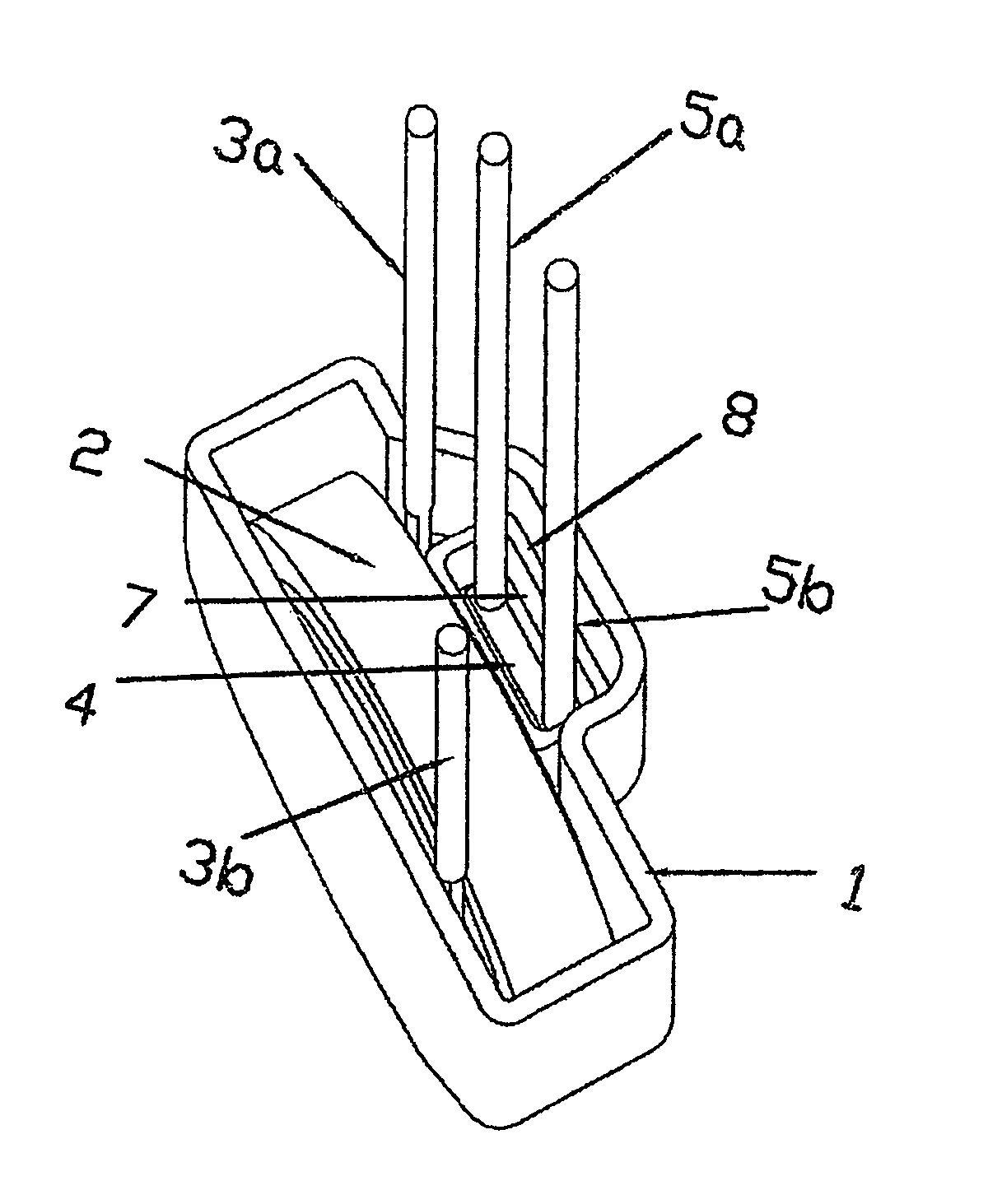
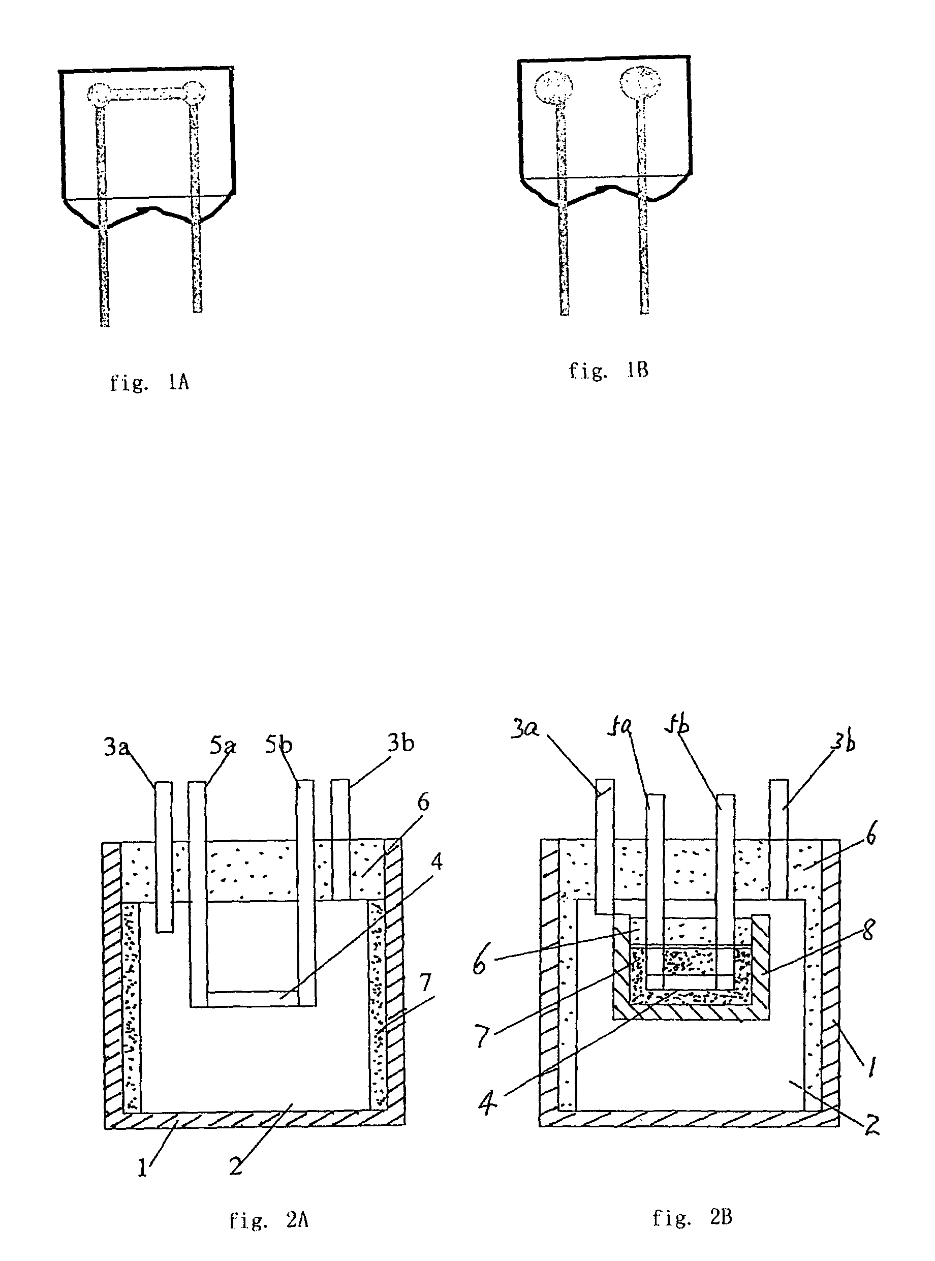
[0047]Shown in FIG. 2A is the drawing of the basic structure of the first embodiment which comprises a case 1, a varistor 2 and an alloy-type thermal or temperature fuse 4. The varistor 2 and alloy-type thermal fuse 4 are placed in the case 1 with the surface of the varistor 2 being close to the surface of the alloy-type thermal fuse 4. The case 1 is filled with alloy melting promoting agent 7. The opening of the shell or case 1 is sealed by epoxy resin 6 to form the closed chamber. The leads 3 of the varistor and leads 5 of the fuse are extended to the outside of the case 1.

[0048]In use, when the varistor 2 is heated by various causes, the heat is transferred first to the ambient or surrounding alloy melting promoting agent 7 from the surface of the varistor 2 and then is transferred from the melting promoting agent 7 to the alloy-type thermal fuse 4 until the alloy is melted due to the heating and balls-up and shrinks towards the two leads 5a and 5b of the fuse 4 rapid...

embodiment 2

[0049]Shown in FIG. 2B, is the basic structure of the second embodiment which comprises a varistor 2, an alloy-type thermal fuse 4, an outer case 1 and a small inner case 8. The alloy-type thermal fuse 4 and melting promoting agent, e.g. resin 7 are placed in the small inner case 8 which is made of ceramic or other material of high heat conduction and high electrical insulation, the opening of the small inner case 8 being sealed by epoxy resin 6 with the inner side of the small inner case 8 clinging to one surface of the varistor 2. The small inner case 8 and the varistor 2 are placed in the outer case 1 with the opening of the case 1 being sealed by epoxy resin 6 to form the closed cavity.

[0050]When varistor 2 is heated by various causes, heat is transferred from the surface of the varistor 2 to the contacting wall of the inner case 8, and thence into the alloy melting promoting agent 7 that fills the inner case, and then the heat is transferred to the alloy-type thermal fuse 4 unt...

embodiment 3

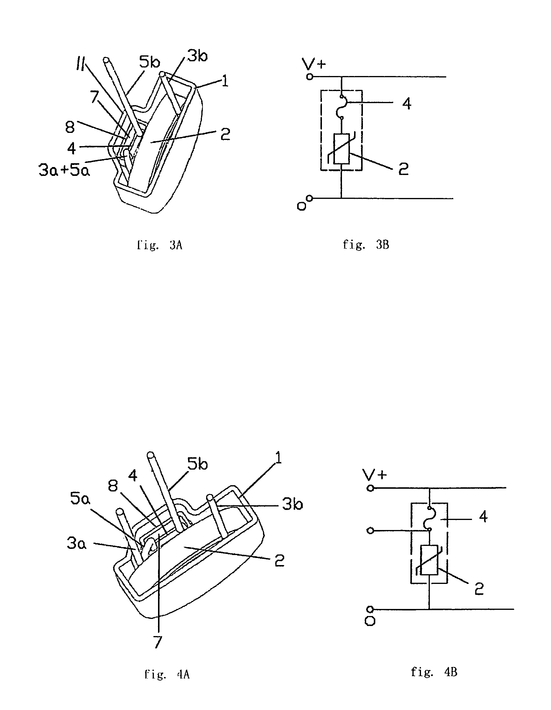
[0051]Shown in FIGS. 3A and 3B, is an embodiment for two leads which comprises a varistor 2, an alloy-type thermal fuse 4, an outer case 1 and an inner small case 8. The front wall of the outer case 1 extends to the outside to form a raised part 11 for accommodating the small case 8 therein. The alloy-type thermal fuse 4 and melting promoting agent such as a resin 7 are placed in the small case 8 which is made of ceramic or other material of high heat conduction and high electrical insulation. The opening of the small case 8 is sealed by epoxy resin 6 with the inner side of the small case 8 clinging to one surface of the varistor 2. The small case 8 and the varistor 2 are placed in the case 1 (as shown in FIG. 2B). The first lead 3a of the varistor 2 is connected with the second lead 5a of the alloy-type thermal fuse 4 and closed in the case. The second lead 3b of the varistor 2 and the first lead 5b of the alloy-type thermal fuse 4 respectively extend to the outside of the case. Th...


PUM

PropertyMeasurementUnit
leakage currentaaaaaaaaaa
distanceaaaaaaaaaa
surface tensionaaaaaaaaaa

Abstract

An electronic protection component incorporates both a varistor and an alloy-type thermal fuse. In one embodiment, a melting promoting agent or flux contacts and surrounds both the varistor and the fuse in common in a shared cavity of a case. In another embodiment, the fuse and the flux are disposed in an inner case, which is disposed in contact with the varistor in an outer case. Thus, the varistor and the thermal fuse are incorporated so that the speed of heat transfer is fast, the response time is fast, and the installation for use is convenient.

Description

[0001]The invention relates to a varistor with built-in alloy-type thermal fuse with thermal failure protection which is particularly applied to zinc oxide varistors and used for over-voltage protection.BACKGROUND OF THE INVENTION[0002]A varistor is broadly used as an over-voltage protection component and surge absorption component of circuit, equipment and components because of its non-linear volt-ampere character. Irrespective whether the varistor is used in power circuitry or electrical circuitry, if transient over-voltage happens frequently, the varistor will operate to suppress over-voltage frequently. At the same time, it will adsorb and release surge energy to protect electrical equipment and components, which will certainly cause the varistor to fail or be damaged. When the varistor suffers transient over-voltage, it will be rapidly partially destroyed and causing fire. Nowadays, most varistors with thermal failure protection have some disadvantages such as the following: So...

Claims


Application Information

Patent Timeline
Patent Type & Authority Patents(United States)
IPC IPC(8): H02H1/00
CPCH01C7/126H02H9/042H01C7/1006H01C7/12H01C7/10H01H37/761
Inventor XU, ZHONGHOU
Owner XIAMEN SET ELECTRONICS
Why Eureka
Try Eureka