
Rolling die of ballscrew

A ball screw and mold technology, which is used in household appliances, metal rolling, manufacturing tools, etc., can solve the problems of shortening the durability of rolling molds, reducing the performance of roundness and shape transformation, and peeling off the machined surface.

Inactive Publication Date: 2004-03-10
NSK LTD
View PDF0 Cites 6 Cited by
  • Summary
  • Abstract
  • Description
  • Claims
  • Application Information

AI Technical Summary

Problems solved by technology

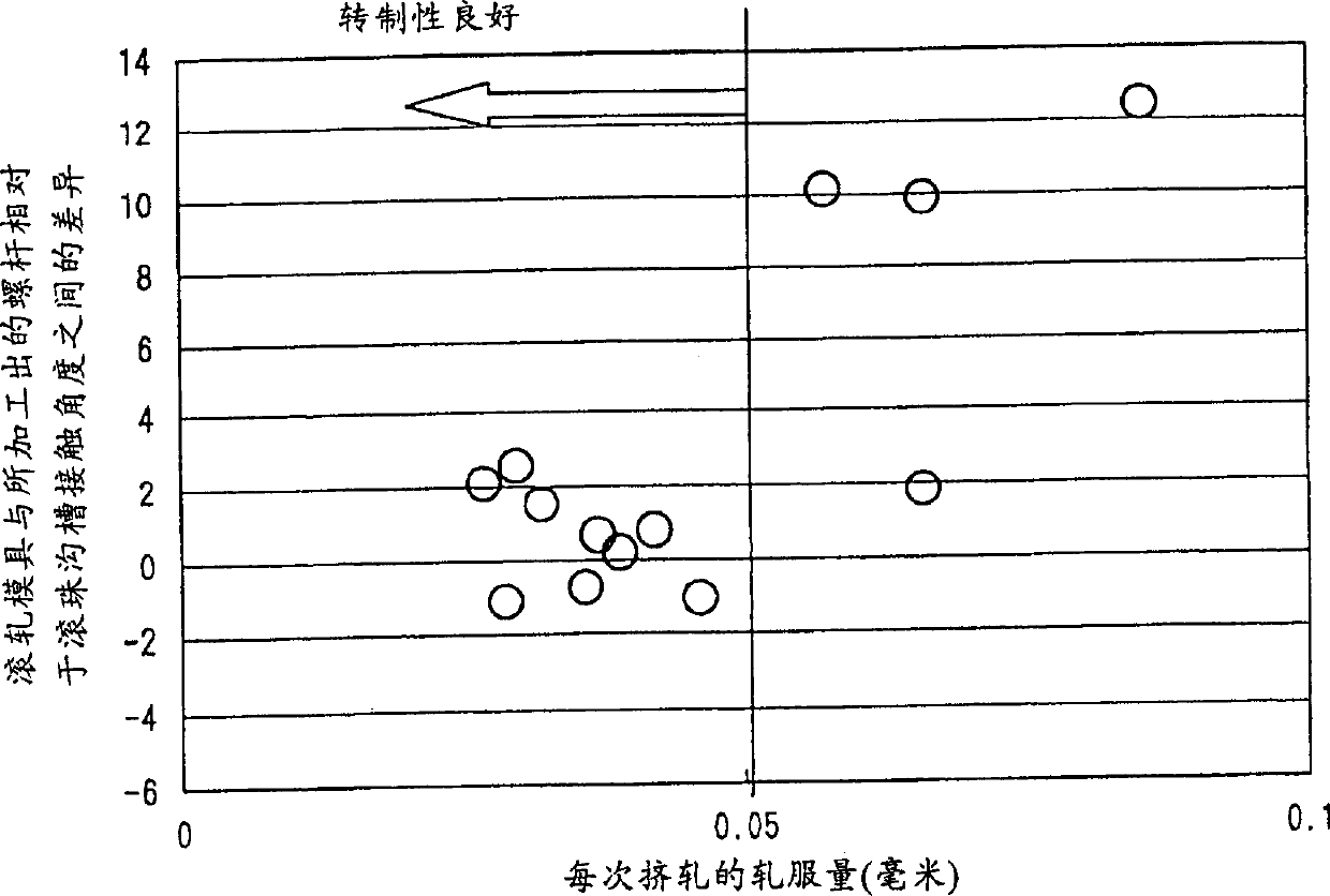
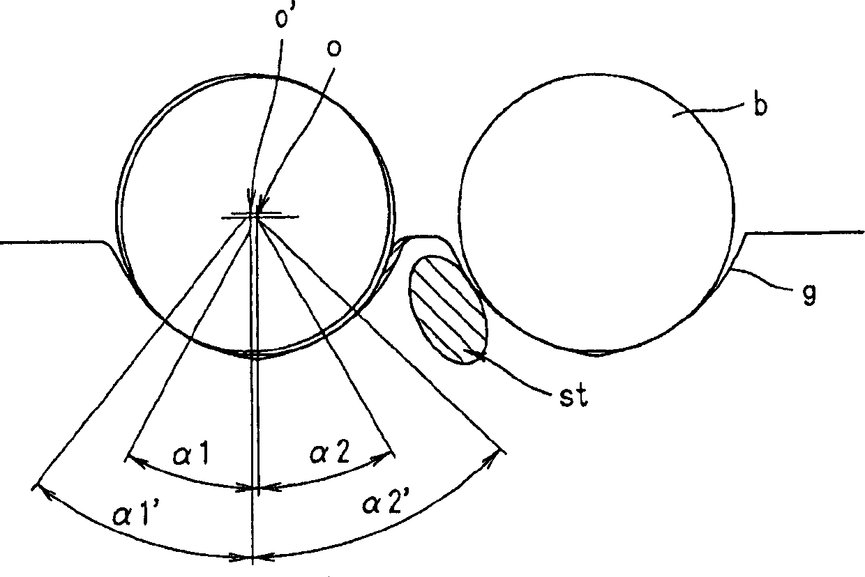
[0003] However, when a thread rolling die shown in FIG. 7 is used to manufacture a screw whose upper ball groove has a pitch larger than the ball diameter, that is, as shown in FIG. 9, the pitch p of the ball groove g on the screw bs It is 1.7 times or larger than the diameter dB of the ball b, which may make the amount of billet rolled by the thread rolling die larger each time
This will increase the possibility that the circularity deviation and shape transfer property of the ball grooves to be rolled and formed on the screw stock may be degraded, thereby failing to meet necessary technical requirements
In order to meet the necessary technical requirements, in the case of increasing the length of the introduction part of the rolling die to thereby reduce the amount of billet rolling per squeeze, the number of processing operations is increased, thereby causing the screw blank to harden through the processing operation, Thereby spalling may occur on the machined surface of the screw blank
[0004] Also, in the case of rolling and processing a ball groove on a screw blank using a rolling die shown in FIG. Concentration, which will shorten the durable life of the rolling die

Method used


Image

  • Rolling die of ballscrew
  • Rolling die of ballscrew
  • Rolling die of ballscrew

Examples


Embodiment Construction

[0021] Next, an embodiment of a rolling die for a ball screw according to the present invention will be described with reference to the accompanying drawings. Incidentally, in this embodiment, the same components as those in the conventional rolling die shown in FIG. 7 are given the same reference numerals, and thus their detailed descriptions are omitted here.

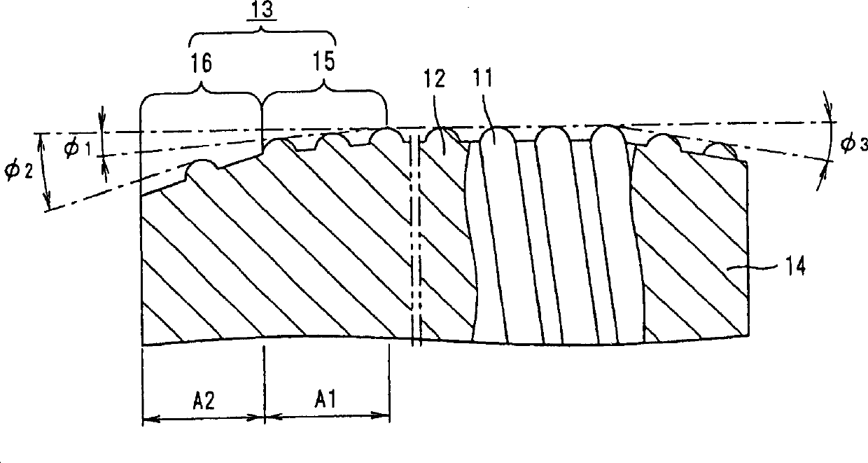
[0022] Fig. 1 is a sectional view of a part of a rolling die for a ball screw according to an embodiment of the present invention. As shown in FIG. 1 , the lead-in portion 13 on the ball screw rolling die according to the present embodiment is composed of two frustoconical portions 15 and 16 combined. For the two frustoconical portions 15 and 16, their respective blank contact angles φ1 and φ2 with respect to the screw blank differ from each other. Specifically, the blank contact angle φ1 of the frustoconical portion 15 adjacent to the cylindrical portion 12 has the following relationship with respect to the blank co...


PUM


Abstract

The roller for a ball spindle comprises a cylindrical section with a helical form protrusion formed in an outer circumferential face in order to form a helical ball track in the raw material of the spindle shaft, and a conical lead-in section formed in one end section of the cylindrical section and comprising a number of truncated cone shaped sections, the contact angle of which in relation to the raw material of the spindle shaft is established becomes continuously larger in the direction from the cylindrical section to the end of the lead-in section.

Description

technical field [0001] The invention relates to a rolling die of a ball screw, which is used for manufacturing a screw in the ball screw. Background technique [0002] Typically, the screw in a ball screw is formed from a rod-shaped screw blank made of metal and includes a helical ball groove formed therein. As a method for manufacturing such a screw, a method is disclosed in JP-A-9-133195 in which there is a rolling die 10 as shown in FIG. 7 . That is, a rolling die 10 is pressed against the screw blank w as shown in FIG. The rolling die 10 also includes a conical lead-in portion 13 and a conical exit portion 14 respectively formed at both ends of the cylindrical portion 12 . In this pressing state, one of the rolling die 10 and the screw blank w is rotated relative to the other, thereby rolling and machining a ball groove g on the screw blank w. The method disclosed in the cited publication is a so-called through-feed type rolling method using the through-feed phenomeno...

Claims


Application Information

Patent Timeline
Patent Type & Authority Applications(China)
IPC IPC(8): F16H25/24B21H3/04B21H7/18
CPCB21H7/187B21H3/04
Inventor 小池悦雄三宫仁志
Owner NSK LTD
Learn More