Photoelectric rotary coder
一种旋转编码器、光电式的技术,应用在转换传感器输出、仪器、采用光学装置传递传感构件等方向,能够解决部件个数增加、制约装置小型化、不能扩大投光部分光束等问题,达到提高平行度的效果
- Summary
- Abstract
- Description
- Claims
- Application Information
AI Technical Summary
Problems solved by technology
Method used
Image
Examples
Embodiment approach 1
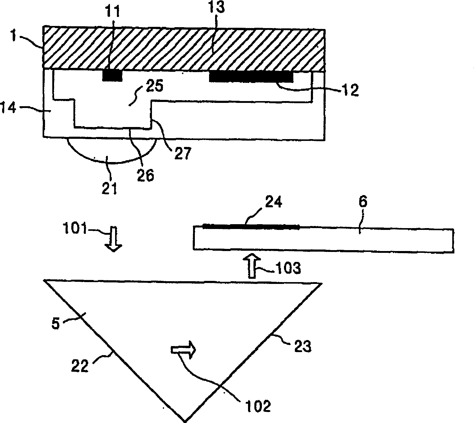
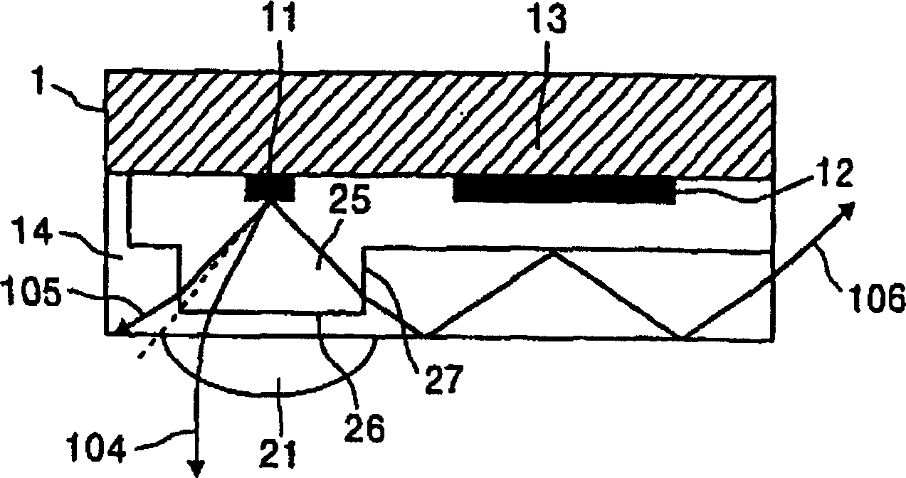
[0048] figure 1 A structural diagram of a main part of a photoelectric rotary encoder according to Embodiment 1 of the present invention is schematically shown. In the figure, 1 is a light projecting and receiving module, on which a light projecting element 11 and a light receiving element 12 are installed on a substrate 13, and an optical element 14 is assembled on the substrate 13 and covers the light projecting element 11 and the light receiving element 12. On the surface of the optical element 14 is provided a first lens 21 utilizing a refractive difference with the surroundings, and inside is provided a cylindrical cavity 25 having an outer diameter smaller than that of the first lens 21 and having an opening surface 26 and a side surface 27 .
[0049] figure 1 Among them, 5 is a turning part, which has a reflective surface 22, which reflects the light beam 101 of the outgoing light from the light projecting element 11 converged by the first lens 21; the reflective surfa...
Embodiment approach 2
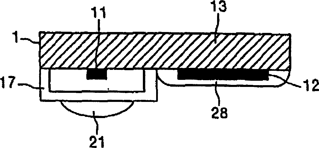
[0056] image 3 A configuration diagram schematically showing a light emitting and receiving module of a photoelectric rotary encoder according to Embodiment 2 of the present invention. and figure 2 Compared with the first embodiment, only the light projecting element 11 is covered by the optical element 17 , and the light receiving element 12 is closed by the silicon part 28 . For the composition of the turning part 5, the circular plate 6, etc., and figure 1 Same, therefore, not shown. According to this configuration, the shape of the optical element can be made smaller, and therefore, there is an advantage that the light emitting and receiving module 1 can be further downsized.
[0057] Thus, according to Embodiment 2, since the light projecting element is covered with an optical element and the light receiving element is sealed with silicon, a further downsized photoelectric rotary encoder can be obtained.
Embodiment approach 3
[0059] Figure 4 A configuration diagram schematically showing a light emitting and receiving module of a photoelectric rotary encoder according to Embodiment 3 of the present invention. exist figure 1 In the first embodiment, the fixed slit 51 formed by the V-groove is provided in the part of the optical element 14 facing the light receiving element 12, so that the incident angle of the incident light from the side of the folded part is 45 degrees, and the incident light is selective. ground shade. For the structure of the reentrant part 5, the circular plate 6, etc., and figure 1 Same, therefore, not shown.
[0060] For example, when the optical element 14 is made of polycarbonate with a refractive index of 1.58, the critical angle is 39.3 degrees, so the parallel light incident on the V-groove portion of the fixed slit 51 is totally reflected and blocked. According to this configuration, the light-shielding slit can be easily formed by processing only the V-groove in th...
PUM
 Abstract
Description
Claims
Application Information
 - R&D
- Intellectual Property
- Life Sciences
- Materials
- Tech Scout
- Unparalleled Data Quality
- Higher Quality Content
- 60% Fewer Hallucinations
Browse by: Latest US Patents, China's latest patents, Technical Efficacy Thesaurus, Application Domain, Technology Topic, Popular Technical Reports.
© 2025 PatSnap. All rights reserved.Legal|Privacy policy|Modern Slavery Act Transparency Statement|Sitemap|About US| Contact US: help@patsnap.com


