Seal device for water pump rotation supporting device for water pump and water pump

A sealing device, technology of water pumps, applied in parts of pumping devices for elastic fluids, seals of engines, pumps, etc.

Inactive Publication Date: 2004-03-24
NSK LTD
View PDF2 Cites 17 Cited by
  • Summary
  • Abstract
  • Description
  • Claims
  • Application Information

AI Technical Summary

Problems solved by technology

That is, in the above-mentioned Figure 5 In Japanese Patent Application Laid-Open No. 11-153096, it is simply described that the front edge of one sealing lip 12c among the three sealing lips 12a, 12b, and 12c constituting the sealing ring 7a and the oil flinger The structure of sliding contact on the outer surface of 11a does not describe specific specifications, etc.

Method used


Image

  • Seal device for water pump rotation supporting device for water pump and water pump
  • Seal device for water pump rotation supporting device for water pump and water pump
  • Seal device for water pump rotation supporting device for water pump and water pump

Examples


Embodiment Construction

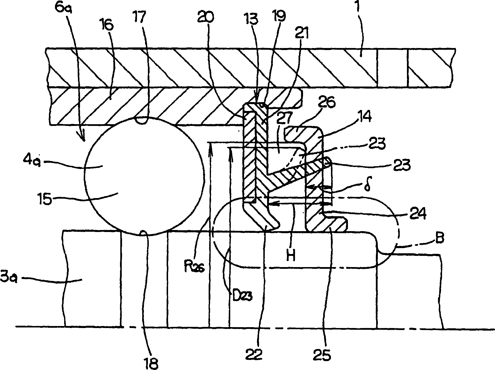
[0026] figure 1 This is the first example showing the embodiment of the present invention. In addition, this example is characterized in that it is provided at the middle portion of the rotating shaft 3a, and the mechanical seal 10 (refer to Figure 4 ) compared with the shape and size of the sealing ring 13 and the flinger 14 at the outer part, through appropriate restrictions, it is difficult for water vapor or hot water passing through the above-mentioned mechanical seal 10 to enter the rolling bearing containing a plurality of rolling elements (balls) 15 Unit 6a side. Because the overall structure of the water pump, etc., the structure and function of other parts include the above-mentioned Figure 4 The structure shown is the same as that of a conventionally known water pump, so the illustration and description of equivalent parts are omitted or simplified, and the following description will focus on the characteristic parts of the present invention and parts that have n...


PUM


Abstract

A seal apparatus is comprised of a seal ring 13 and a slinger 14 in combination to prevent foreign matter from progressing into the rolling bearing 6a. The amount of compression delta of the second seal lip 23, which occurs when the tip edge of the second seal lip 23 of the seal ring 13 comes in contact with the outside surface of the slinger 14, is at least 1 / 10 and up to 7 / 10 the height of the second seal lip 23 in the free state. In addition, the roughness of a portion of the outside surface of the slinger 14 which the tip edge of the second seal lip 23 comes in sliding contact with is from 0.2 mu m to 2.0 mu m in the arithmetic mean Ra, or is from 0.8 mu m to 8.0 mu m in the maximum height Ry. Consequently, a structure of a water pump is provided without increasing the cost thereof; or without enlarging the size to improve the durability of the water pump.

Description

technical field [0001] The sealing device for a water pump, the rotary support device for a water pump, and the water pump according to the present invention relate to improvement of a sealing device for a water pump for circulating cooling water of an automobile engine. Background technique [0002] As a water pump for circulating cooling water of an automobile engine, for example, in Japanese Patent Application Laid-Open No. 8-254213, the following Figure 4 A device constructed as shown. The cylindrical casing 1 is fixed to the cylinder block of the engine by using the mounting flange 2 formed on the outer peripheral surface of the inner end (inner relative to the axial direction refers to the side close to the engine, which is the right side of each figure). . On the inner diameter side of the casing 1, the rotating shaft 3 passes through a rolling bearing composed of a ball bearing 4 on the inside and a rolling bearing 5 on the outside (the side away from the engine re...

Claims


Application Information

Patent Timeline
Patent Type & Authority Applications(China)
IPC IPC(8): F04D29/046F04D29/049F04D29/10F04D29/12F04D29/70F16C33/78
CPCF04D29/049F16C2360/42F16C19/49F04D29/126F04D29/106F04D29/0462F16C33/7859F16C33/784F16C2360/44F04D29/12
Inventor 池谷正道
Owner NSK LTD
Why Eureka
Try Eureka