

Audio decoder and audio decoding method
A technology of speech decoding and decoding signals, which is applied in the directions of instruments, speech analysis, code conversion, etc., and can solve problems such as difficulties in detecting stable noise areas
- Summary
- Abstract
- Description
- Claims
- Application Information
AI Technical Summary
Problems solved by technology
Method used
Image

Examples
no. 1 example
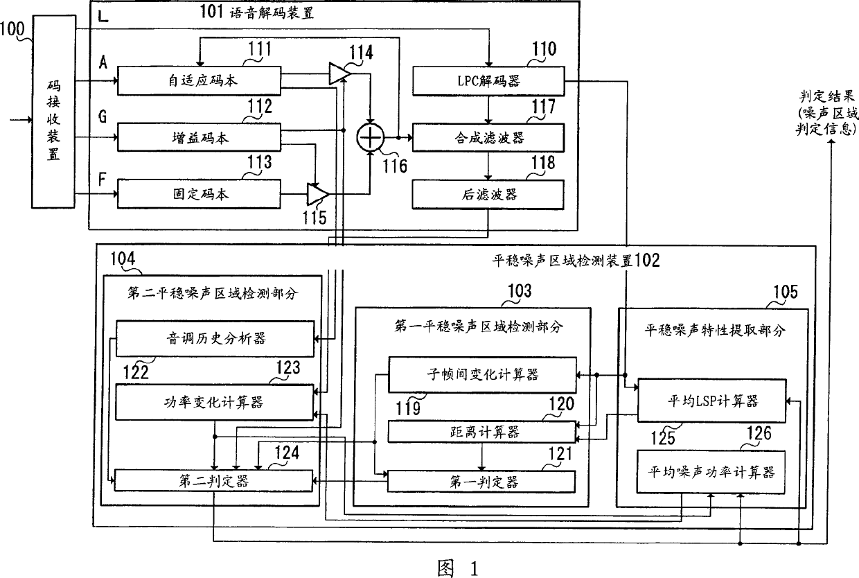
[0023] FIG. 1 shows the structure of a stationary noise area determination device according to a first embodiment of the present invention.
[0024] An encoder (not shown) first uses an input digital signal, performs analysis and quantization of LPC (Linear Prediction Coefficient), pitch search, fixed codebook search, and gain codebook search, and transmits LPC code (L), pitch period (A ), fixed codebook index (F) and gain codebook index (G).
[0025] The code receiving device 100 receives an encoded signal transmitted from an encoder, and separates a code L representing LPC, a code A representing an adaptive code vector, a code G representing gain information, and a code F representing a fixed code vector from the received signal. The separated code L, code A, code G and code F are output to the speech decoding device 101 . Specifically, the code L is output to the LPC decoder 110 , the code A is output to the adaptive codebook 111 , the code G is output to the gain codebook...
no. 2 example
[0098] FIG. 5 shows the structure of a stationary noise post-processing device according to a second embodiment of the present invention. In FIG. 5 , the same parts as in FIG. 1 are assigned the same reference numerals as in FIG. 1 , and specific descriptions thereof are omitted.
[0099]The stationary noise post-processing device 200 includes a noise generating section 201 , an adder 202 and a tuning section 203 . Stationary noise post-processing device 200 adds the pseudo-stationary noise signal generated in noise generating part 201 and the post-filter output signal from speech decoding device 101 in adder 202, and adds the post-filter output signal through adding in tone tuning part 203. The filter output signal performs tuning to adjust power, and outputs a post-processed post-filter output signal.
[0100] The noise generation section 201 includes an excitation generator 210 , a synthesis filter 211 , an LSP / LPC converter 212 , a multiplier 213 , a multiplier 214 , and ...
no. 3 example
[0122] FIG. 6 shows the structure of a stationary noise post-processing device according to a third embodiment of the present invention. In FIG. 6, the same parts as in FIG. 5 are assigned the same reference numerals as in FIG. 5, and specific descriptions thereof are omitted.
[0123] This device includes the structure of the stationary noise post-processing device 200 as shown in FIG. 2, and also provides a memory for storing parameters required for generating a noise signal and tuning when a frame is deleted, a frame deletion blanking processing control part, and a control section for Switch for frame deletion blanking processing.
[0124] The stationary noise post-processing device 300 includes a noise generating section 301 , an adder 202 , a tuning section 303 , and a frame deletion blanking process control section 304 .
[0125] Noise generation part 301 comprises the structure of noise generation part 201 as shown in Figure 5, and also provides: memory 310 and 311, st...
PUM
 Abstract
Description
Claims
Application Information