Heat cutting working machine and cutting method utilizing the same thermal cutting working machine

A cutting method and processing machine technology, applied to metal processing machinery parts, metal processing equipment, welding/cutting auxiliary equipment, etc., can solve problems such as inclination, large splashes, and rising production costs, so as to improve the durability and improve the working environment , Productivity improvement effect

Inactive Publication Date: 2004-04-07
KOMATSU SANKI
View PDF2 Cites 7 Cited by
  • Summary
  • Abstract
  • Description
  • Claims
  • Application Information

AI Technical Summary

Problems solved by technology

[0011] (1) In the actual plasma cutting, such as Figure 7 As shown, the workpiece slices chopped on the workbench lost the support of the workpiece support frame of the above workbench, and could not maintain the level and tilted
Since the protective cover B installed around the cutting torch moves horizontally at its lower end in a state close to the workpiece, even if the workpiece is slightly tilted, the lower part of the protective cover B and the above-mentioned upright There is a risk of damage to the protective cover B due to the interference of the workpiece
In addition, the interference between the lower part of the protective cover B and the above-mentioned workpiece will cause excessive load to the movement of the cutting torch in the horizontal direction, causing problems such as stopping the machine
[0012] (2) Corresponding to this problem, although it has been shown that as the material constituting the protective cover B, it is preferable to use a thin steel plate with moderate flexibility, a thin stainless steel plate, or a synthetic resin sheet with fire resistance, etc. When C interferes, the wall of the protective cover B may be greatly bent, and if the frequency of this interference is considered, it may still form an obstacle to the movement of the cutting torch
However, even if the protective cover is made of a thin steel plate, a thin stainless steel plate, or a fire-resistant synthetic resin sheet in the conventional technology, although the service life is longer than that of the above-mentioned heat-resistant cloth, it cannot be penetrated anyhow. The largest splash that occurs during fusion cutting will also melt and fall off, and the tiny gap between the workpiece and the lower end of the protective cover cannot maintain a close bond
Therefore, the effect of shielding droplets cannot be exerted for a long time, so it is not practical
[0015] (4) In addition, in order to easily observe the state of the plasma arc and the processing state of the workpiece, the side walls of the shield are preferably made of transparent synthetic resin plates, but in this case, droplets may adhere to the synthetic resin plate and melt it, so its transparency will be damaged in a short time
also impractical
[0016] (5) Furthermore, although the amount of cutting varies, it is necessary to remove the cap of the torch several times a day, and replace consumables such as nozzles and electrodes attached to the front end of the torch.
This has brought about the problem of rising production costs

Method used


Image

  • Heat cutting working machine and cutting method utilizing the same thermal cutting working machine
  • Heat cutting working machine and cutting method utilizing the same thermal cutting working machine
  • Heat cutting working machine and cutting method utilizing the same thermal cutting working machine

Examples


Embodiment Construction

[0042] Embodiments of the thermal cutting machine and the cutting method using the thermal cutting machine according to the present invention will be described below with reference to the accompanying drawings.

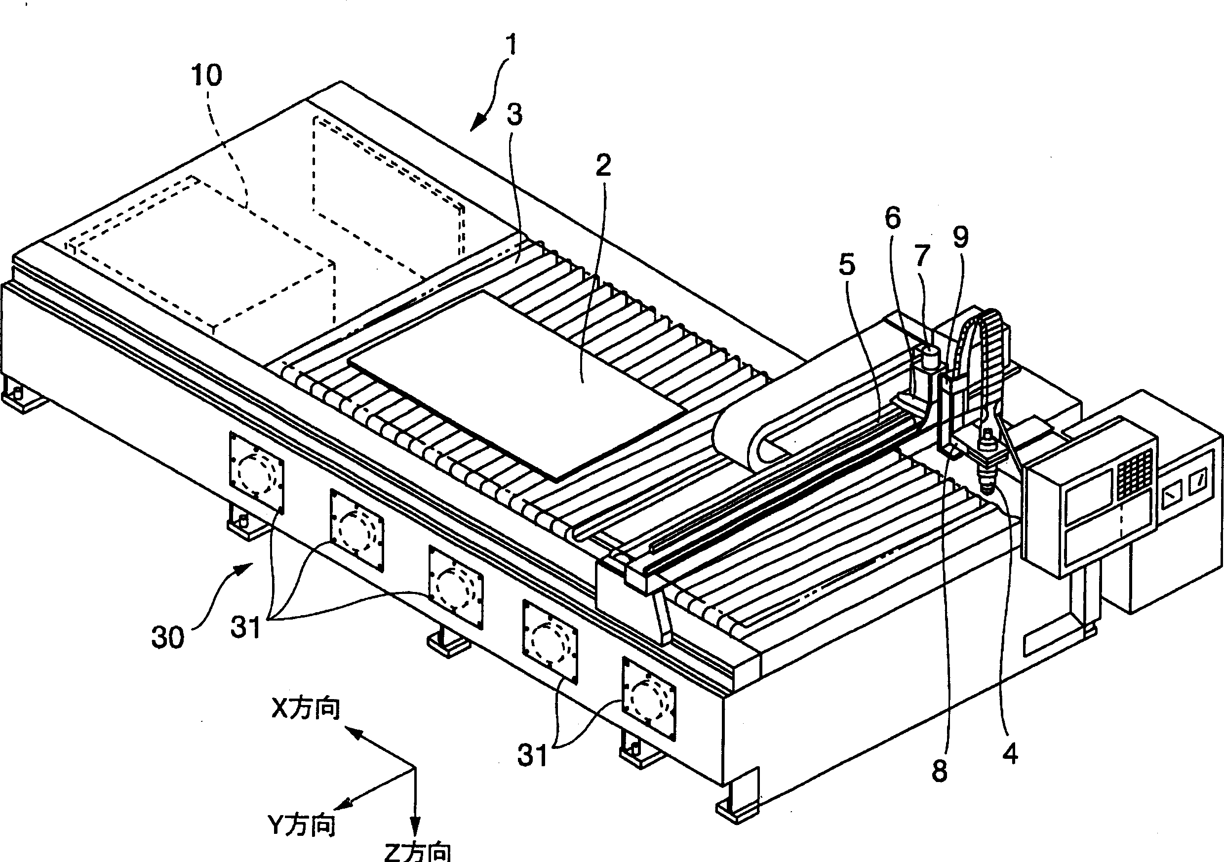
[0043] figure 1 A perspective view of a whole plasma cutting machine given as an example of a thermal cutting machine in one embodiment of the present invention is shown in .

[0044] The plasma cutting machine 1 of the present embodiment is provided with a cutting workbench 3 supporting the workpiece 2. At the bottom of the cutting workbench 3, there are a plurality of push-pull blowers 31 arranged on the opposite side parts of the workbench 3. Dust collector 30 that collects droplets, smoke, high-pressure gas (exhaust smoke), etc. generated during cutting. On the top of the above-mentioned cutting workbench 3, a Y-axis vehicle frame 5 that can freely walk along the X-axis direction that is perpendicular to each other in the workbench surface as one of the two axes...


PUM


Abstract

A thermal cutting machine and a cutting method using the same are described, which employ a simple, long-life torch hood for effectively shutting off spatter, the torch hood enabling easy supervision of the cut condition of a workpiece and easy replacement of the consumable parts of the torch. In the thermal cutting machine for cutting a metal by a plasma arc or laser beam generated from the torch, a hood liftable by an actuator is disposed so as to surround the torch and a control unit is provided for giving an instruction to the actuator to lower the hood to a torch-shielding position.

Description

technical field [0001] The present invention relates to a thermal cutting machine such as a plasma cutting machine or a laser cutting machine, and a cutting method using the thermal cutting machine. In more detail, it is mainly about the technology of masking the droplets generated when cutting. Background technique [0002] Traditionally, when a thermal cutting machine such as a plasma cutting machine or a laser cutting machine is used for thermal cutting processing of a metal sheet (hereinafter referred to as "the workpiece"), the molten material of the cut part of the workpiece generated by the plasma arc or laser, etc., will be Sprays (sprays of molten metal) are formed due to the air pressure of the plasma gas ejected from the cutting torch and are scattered around. The smoke (metal vapor) and noise generated at the same time deteriorate the working environment in the factory. In order to solve this problem, various technologies have been developed to shield smoke, arc...

Claims


Application Information

Patent Timeline
Patent Type & Authority Applications(China)
IPC IPC(8): B23K5/22B23K9/32B23K10/00B23K26/12B23K26/16B23K26/38B23K37/00B23K37/04B23K37/06
CPCB23K26/12B23K37/06B23K37/006B23K10/00B23K26/38B23K5/22B23K26/422B23K37/0461B23K26/128B23K26/702
Inventor 山口义博加端哲也
Owner KOMATSU SANKI
Why Eureka
Try Eureka