Automatic speed regulator hydraulic controller and controlling method for abrading connector thereof

A technology for frictional engagement devices and automatic transmissions, which is applied in transmission control, engine control, electrical control, etc., and can solve problems such as fluctuations in the rate of change of turbine speed

Inactive Publication Date: 2004-04-21
TOYOTA JIDOSHA KK
View PDF1 Cites 23 Cited by
  • Summary
  • Abstract
  • Description
  • Claims
  • Application Information

AI Technical Summary

Problems solved by technology

[0003] However, with such a hydraulic control device for a vehicle automatic transmission, when a factor that changes the input torque of the engine is generated due to operations such as fuel cut control or air conditioner control during a power cut upshift, the rate of change of the turbine speed occurs. fluctuation

Method used


Image

  • Automatic speed regulator hydraulic controller and controlling method for abrading connector thereof
  • Automatic speed regulator hydraulic controller and controlling method for abrading connector thereof
  • Automatic speed regulator hydraulic controller and controlling method for abrading connector thereof

Examples


Embodiment Construction

[0029] Various exemplary embodiments will be described in detail below in conjunction with the accompanying drawings.

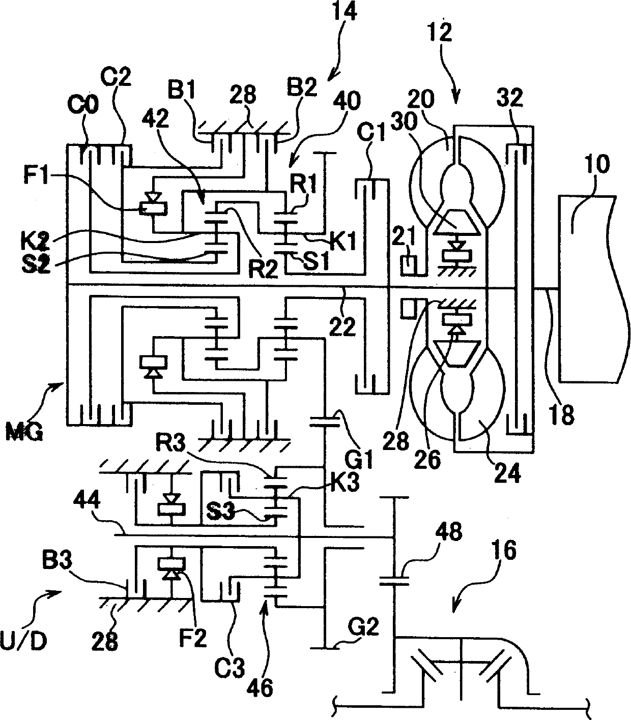
[0030] FIG. 1 is a schematic diagram of a transverse vehicle drive device of a vehicle such as a FF (Front Engine Front Drive) vehicle. An output of an engine 10 such as an internal combustion engine such as a gasoline engine is transmitted to unillustrated drive wheels ( front wheel). The hydraulic torque converter 12 includes a pump wheel 20 connected with the crankshaft 18 of the engine 10, a turbine 24 connected with the input shaft 22 of the automatic transmission 14, and a casing fixed as a non-rotating part through a one-way clutch 26. A stator 30 on 28 and a lock-up clutch 32 directly connect crankshaft 18 to input shaft 22 via a buffer (not shown). A mechanical oil pump 21 such as a gear pump is connected to the impeller 20 . The oil pump 21 is driven by the engine 10 together with the pump wheel 20 to generate hydraulic pressure for gear shifting...


PUM


Abstract

The hydraulic pressure control mechanism for a change to a higher gear in a motor vehicle automatic transmission system with a series of hydraulic friction clutches has a first system (102) to determine whether the upward gear change command has been started while there is no pressure on the accelerator pedal, a second system (104) to determine whether a factor modifying an automatic transmission input torque has been generated, and a correction command system to correct the engagement pressure of the predetermined hydraulic friction clutch in conformity with the modification factor. The mechanism also has a computer (106) to calculate the gear selection value on the basis of the vehicle's actual speed, and a system to determine a differential value between the rotational speed of the transmission input shaft and synchronised speed.

Description

technical field [0001] The present invention relates to a hydraulic control device of a vehicle automatic transmission and a control method of a hydraulic friction engagement device of a vehicle automatic transmission, when performing a predetermined upshift by increasing the engagement pressure of a predetermined hydraulic friction engagement device, by A factor changing the input torque of the transmission that occurs during a power cut upshift (power cut upshift) corrects the engagement pressure to suppress upshift shock (vibration). Background technique [0002] JP-A-2001-124192 discloses a hydraulic control device for performing scheduled upshifts by increasing the engagement pressure of a predetermined hydraulic friction engagement device in a vehicle automatic transmission by selectively engaging a plurality of hydraulic friction engagement devices. Friction engagement for gear shifting. The hydraulic control device performs the following 6 steps. In a first step, i...

Claims


Application Information

Patent Timeline
Patent Type & Authority Applications(China)
IPC IPC(8): B60W10/04B60W10/00B60W10/02B60W10/06B60W10/10F02D29/00F02D29/04F02D41/04F02D41/12F02D41/32F16H59/14F16H59/18F16H59/42F16H59/44F16H61/04F16H61/06F16H61/686F16H63/50
CPCF16H61/686F16H2061/0496F16H2059/462F16H2306/52F16H61/061
Inventor 坂本尚之佐藤利光野本久德木村弘道杉村敏夫和田真纯
Owner TOYOTA JIDOSHA KK
Why Eureka
Try Eureka