Ultrasonic detector ultrasonic transducer, examining instrument and ultrosonograhping device
A detection device, ultrasonic technology, applied in the use of sound waves/ultrasonic waves/infrasonic waves to analyze solids, use sound waves/ultrasonic waves/infrasonic waves for material analysis, and measurement devices, etc. It can solve the problem of small connection terminals, internal detection of objects that are difficult to detect, and abnormalities Insufficient judgment ability, etc.
- Summary
- Abstract
- Description
- Claims
- Application Information
AI Technical Summary
Problems solved by technology
Method used
Image
Examples
no. 1 Embodiment
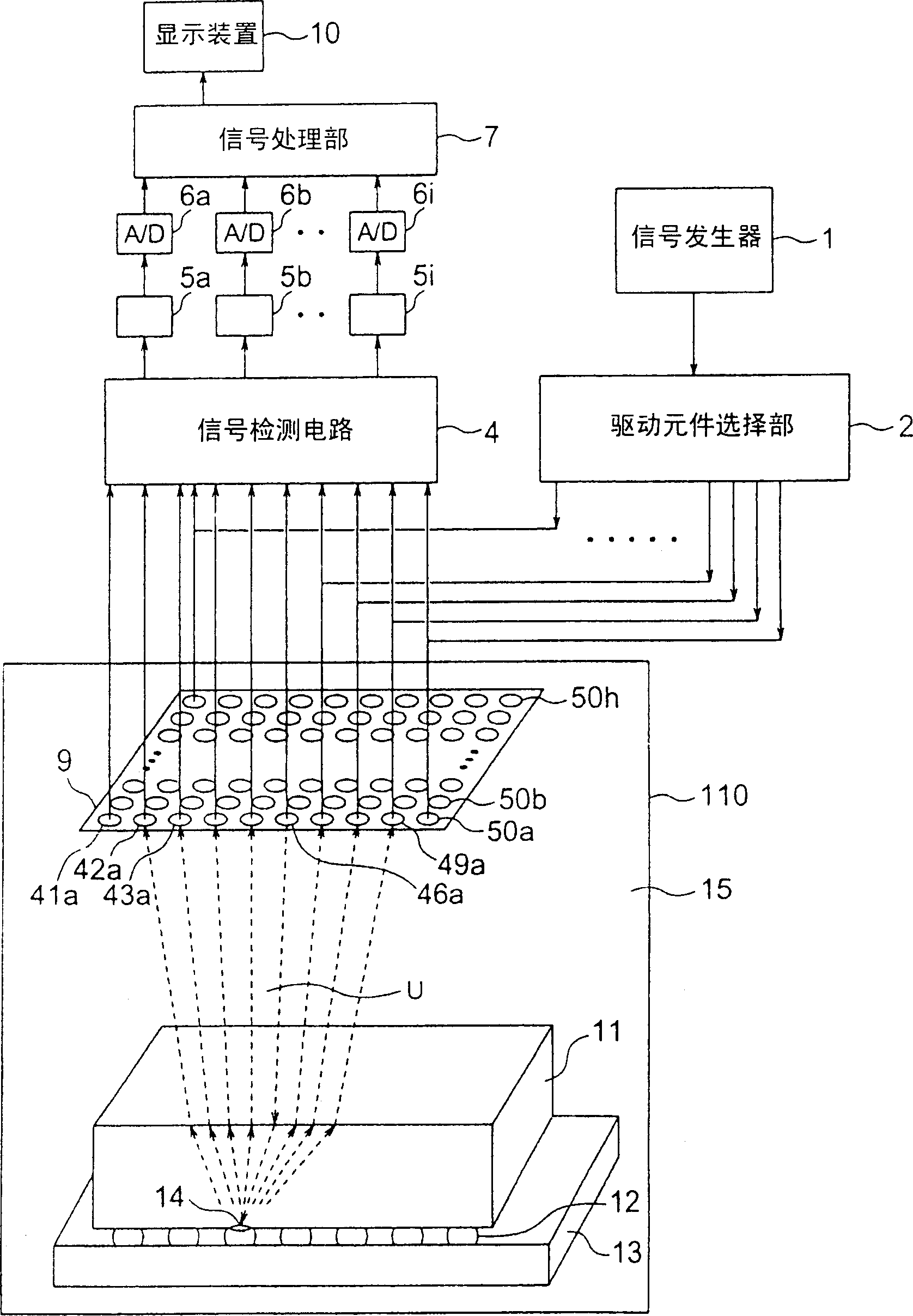
[0086] figure 1 It is a structural diagram explaining the structure of the ultrasonic detection apparatus concerning the 1st Example of this invention. Such as figure 1 As shown, the ultrasonic detection device includes: ultrasonic transducer 9; signal generating part 1; drive element selection part 2; signal detection circuit 4; amplifiers 5a, 5b, ..., 5i; , 6i; the signal processing unit 7, the display device 10, and the detection container 110. Water 15 is accommodated in the detection container 110, and the ultrasonic transducer 9, the semiconductor chip 11, the wiring substrate 13, and the connecting solder 12 (hereinafter referred to as the semiconductor chip) as the detection object (ultrasonic irradiation object) are arranged immersed in the water 15. 11. The wiring substrate 13 and the connecting solder 12 are collectively referred to as the semiconductor chip 11, etc.).
[0087] The ultrasonic transducer 9 is a device in which a plurality of piezoelectric conversi...
no. 2 Embodiment
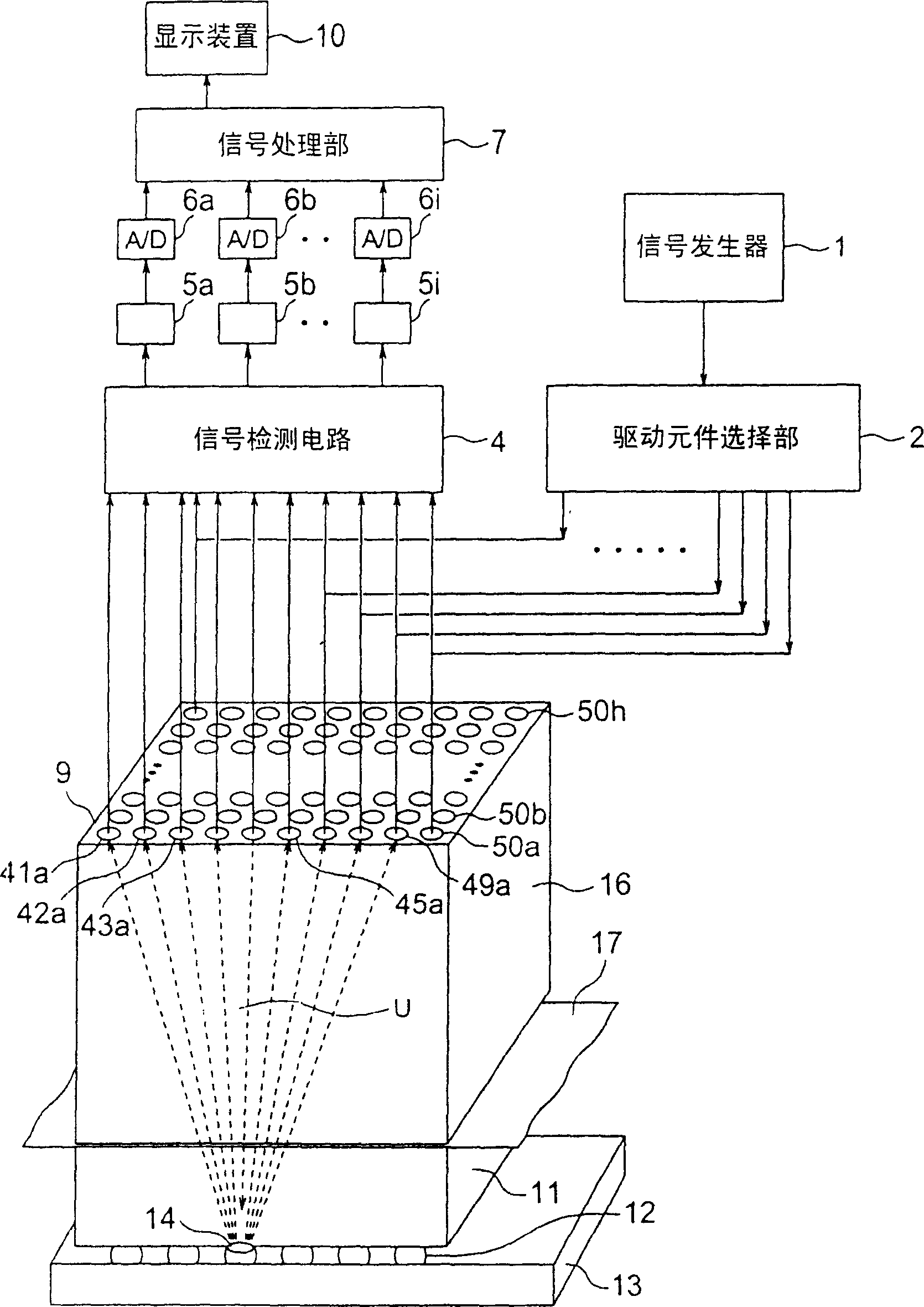
[0101] image 3 It is a figure explaining the structure of the ultrasonic detection apparatus concerning the 2nd Example of this invention. exist image 3 In , components that have already been described are given the same numbers, and descriptions of the components and operations are omitted. This embodiment differs from the above-mentioned first embodiment in that the object to be detected is irradiated with ultrasonic waves not by water but by using a block material.
[0102] Such as image 3 As shown, the ultrasonic transducer 9 is constructed with a shoe material 16 as a substrate. Further, the block 16 is provided with a coupling medium 17 on its back surface, and the semiconductor chip 11 or the like to be detected is pressed by the coupling medium 17 . The bulk material 16 is made of the same material as that of the semiconductor chip 11 (for example, silicon, epoxy resin, ceramics, etc.). The coupling medium 17 may be of the material and thickness already describ...
no. 3 Embodiment
[0107] Figure 4 It is a configuration diagram illustrating the configuration of an ultrasonic testing device related to an embodiment of the present invention. exist Figure 4 In , the components already described are given the same numbers, and their structures and operations are omitted. In this embodiment, the piezoelectric conversion part is directly formed on the back surface (opposite to the functional surface) of the semiconductor chip 11a to be tested, and its upper electrode is contacted through the contact terminal to supply the driving voltage and take out the generated voltage.
[0108] Such as Figure 4 As shown, a common electrode 58 is formed on the back surface of the semiconductor chip 11a by, for example, sputtering, and piezoelectric layers 60a, 60b, 60c, 60d, . . . are formed in a matrix on the common electrode 58 . Upper electrodes 59a, 59b, 59c, 59d, . . . are formed on the piezoelectric layer 60a and the like. For example, the piezoelectric layer 60...
PUM
| Property | Measurement | Unit |
|---|---|---|
| thickness | aaaaa | aaaaa |
Abstract
Description
Claims
Application Information
 - R&D
- Intellectual Property
- Life Sciences
- Materials
- Tech Scout
- Unparalleled Data Quality
- Higher Quality Content
- 60% Fewer Hallucinations
Browse by: Latest US Patents, China's latest patents, Technical Efficacy Thesaurus, Application Domain, Technology Topic, Popular Technical Reports.
© 2025 PatSnap. All rights reserved.Legal|Privacy policy|Modern Slavery Act Transparency Statement|Sitemap|About US| Contact US: help@patsnap.com


