Supercharge Your Innovation With Domain-Expert AI Agents!

Digital controlled five shaft linked plane intrinsic ring surface scroll tooth cutting machine tool

A plane-enveloping, toroidal worm technology, applied in worms, driving devices, mechanical equipment, etc., can solve problems such as low production efficiency, high workpiece cost, and expensive machine tools

Inactive Publication Date: 2004-05-05
天津百利机械装备集团有限公司 +1
View PDF1 Cites 14 Cited by
  • Summary
  • Abstract
  • Description
  • Claims
  • Application Information

AI Technical Summary

Problems solved by technology

[0002] Now the toroidal worm grinding equipment such as German HNC35TP and the inventor's patent "Numerical Control Four-axis Linkage Toroidal Worm Grinding Machine" [Patent No. ZL 92204765.0], its advantage is that the helical surface of the plane enveloping toroidal worm can be precisely formed at one time , the processed workpiece has high precision and high finish, but its disadvantages are low production efficiency and high cost of machine tools, resulting in high cost of processed workpieces, which cannot meet the growing production needs

Method used


Image

  • Digital controlled five shaft linked plane intrinsic ring surface scroll tooth cutting machine tool
  • Digital controlled five shaft linked plane intrinsic ring surface scroll tooth cutting machine tool
  • Digital controlled five shaft linked plane intrinsic ring surface scroll tooth cutting machine tool

Examples


Embodiment 1

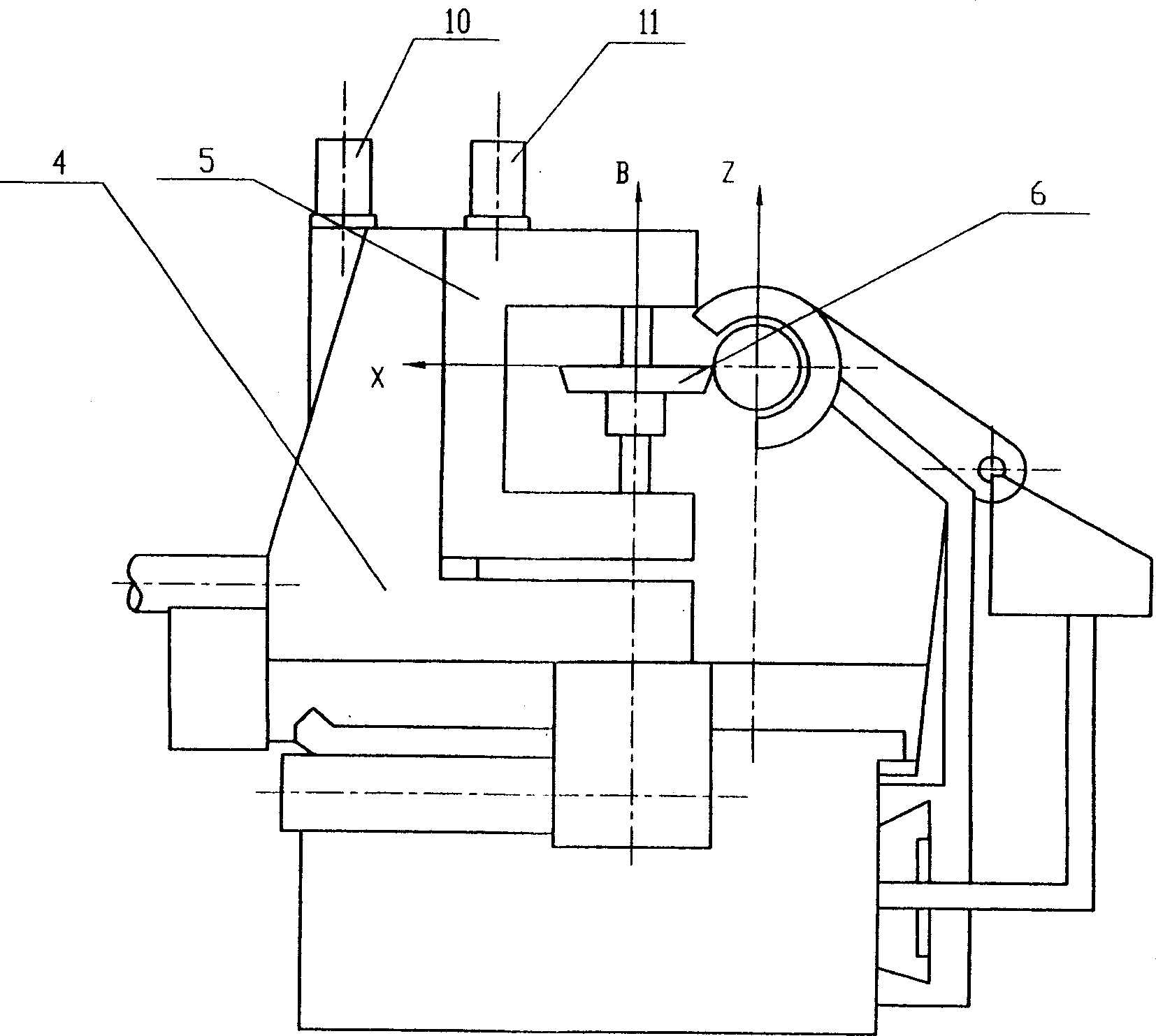
[0027] Embodiment 1: As shown in Figures 4, 5 and 6, a longitudinal slide 3 is installed on the bed 1, and the headstock 2 and tailstock 7 are fixed on the slide 3. The workpiece is installed between the main shaft and the tailstock, the main shaft A controls the rotation of the workpiece by the servo motor 9, the longitudinal slide table moves the workpiece along the Y axis by the servo motor 13, the slide plate 4 is installed on the bed 1, and is driven by the servo motor 12. The sliding plate 4 is fed horizontally along the X axis, and the rotary tool 6 is installed on the tool holder 5 of the vertical guide rail. The rotation of the tool around the B axis is realized by the servo motor 11. Lifting along the Z-axis, the speed of the A-axis can be automatically selected according to the size and speed of the workpiece to ensure a constant cutting speed.

Embodiment 2

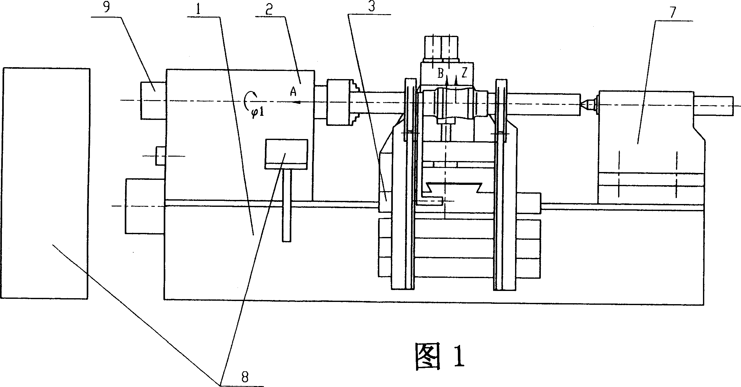
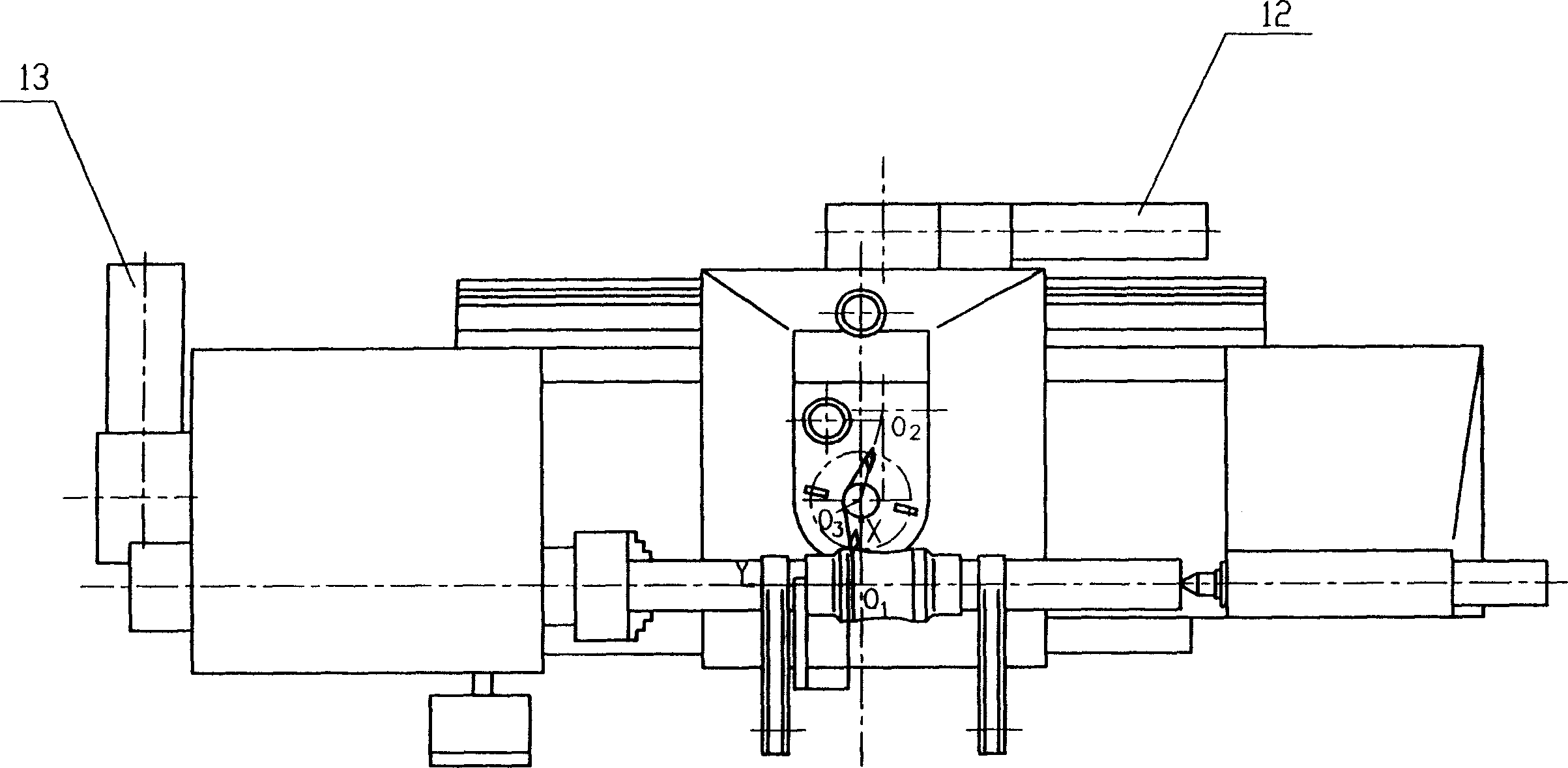
[0028] Embodiment 2: As shown in Figures 1, 2 and 3, the bed 1 is equipped with a headstock 2 and a tailstock 7, the longitudinal slide 3 is installed on the bed 1, the slide 4 is also installed on the longitudinal slide 3, and the vertical guide rail Installed on the sliding plate 4, the tool holder 5 is equipped with a rotary cutterhead, the cutterhead relies on the servo motor 11 to realize the rotation around the B axis, the rotary cutterhead 6 is installed on the vertical guide rail tool holder 5, and the servo motor 10 is used to realize the rotation along the Z axis. Up and down. The rotational speed of the A axis can be automatically selected according to the size and rotational speed of the workpiece, so that the cutting speed of the tool is constant.

[0029] As shown in Figure 7(1), in the five-axis linkage generative motion, the cutting edge of the tool simulates the plane Σ 2 , and ∑ 2 Around K 2 (O 2 ) axis rotation (that is, the rotation of the B axis and th...


PUM


Abstract

A numerally controlled tooth cutting machine tool with 5-shaft linkage to envelope the plane enveloped torus worm is composed of the machine tool and the control cabinet. Said machine tool consists of main body, mainshaft box, longitudinal sliding bench, perpendicular tracks, transverse slide carriage, tail seat, and tool carrier with rotary cutterhead equipped with at least two cutters. Said control cabinet has the control programs for mainshaft, moving and rotation of cutterhead. It has 5-axle (A, Y, X, Z and B) linkage function. Its advantages are high cutting speed up to 200 m / min and high productivity.

Description

technical field [0001] The invention relates to a numerically controlled five-axis linkage plane enveloping torus worm gear cutting machine tool. Background technique [0002] Now the toroidal worm grinding equipment such as German HNC35TP and the inventor's patent "Numerical Control Four-axis Linkage Toroidal Worm Grinding Machine" [Patent No. ZL 92204765.0], its advantage is that the helical surface of the plane enveloping toroidal worm can be precisely formed at one time , the processed workpiece has high precision and high finish, but its disadvantages are low production efficiency and high cost of machine tools, resulting in high cost of processed workpieces, which cannot meet the growing production needs. Contents of the invention [0003] The technical problem to be solved by the present invention is to provide a precisely formed planar enveloping toroidal worm CNC gear cutting machine tool, which improves production efficiency and reduces the cost of the machine to...

Claims


Application Information

Patent Timeline
Patent Type & Authority Applications(China)
IPC IPC(8): B23F13/00B23Q5/20B23Q5/22
Inventor 张亚雄齐麟
Owner 天津百利机械装备集团有限公司
Features
  • R&D
  • Intellectual Property
  • Life Sciences
  • Materials
  • Tech Scout
  • Unparalleled Data Quality
  • Higher Quality Content
  • 60% Fewer Hallucinations
Learn More