Heat excanger with receiver tank, and refrigeration system

A technology of heat exchangers and liquid storage tanks, applied in heat exchange equipment, refrigerators, refrigeration components, etc., can solve problems such as difficult, cumbersome screw tightening operations, troublesome assembly operations, etc., and achieve the effect of simple and correct connection

Inactive Publication Date: 2004-05-05
SHOWA DENKO KK
View PDF4 Cites 14 Cited by
  • Summary
  • Abstract
  • Description
  • Claims
  • Application Information

AI Technical Summary

Problems solved by technology

Therefore, the volume of the liquid storage tank is reduced, which in turn leads to a narrowing of the stable range of the refrigerant recooling state, excessive refrigerant or insufficient refrigerant
Therefore, it is difficult to obtain stable cooling performance
[0015] In addition, since the reservoir 130 is fastened to the block flange 140 with screws, a cumbersome screw tightening operation is required, resulting in cumbersome / difficult assembly operations

Method used


Image

  • Heat excanger with receiver tank, and refrigeration system
  • Heat excanger with receiver tank, and refrigeration system
  • Heat excanger with receiver tank, and refrigeration system

Examples


no. 1 example

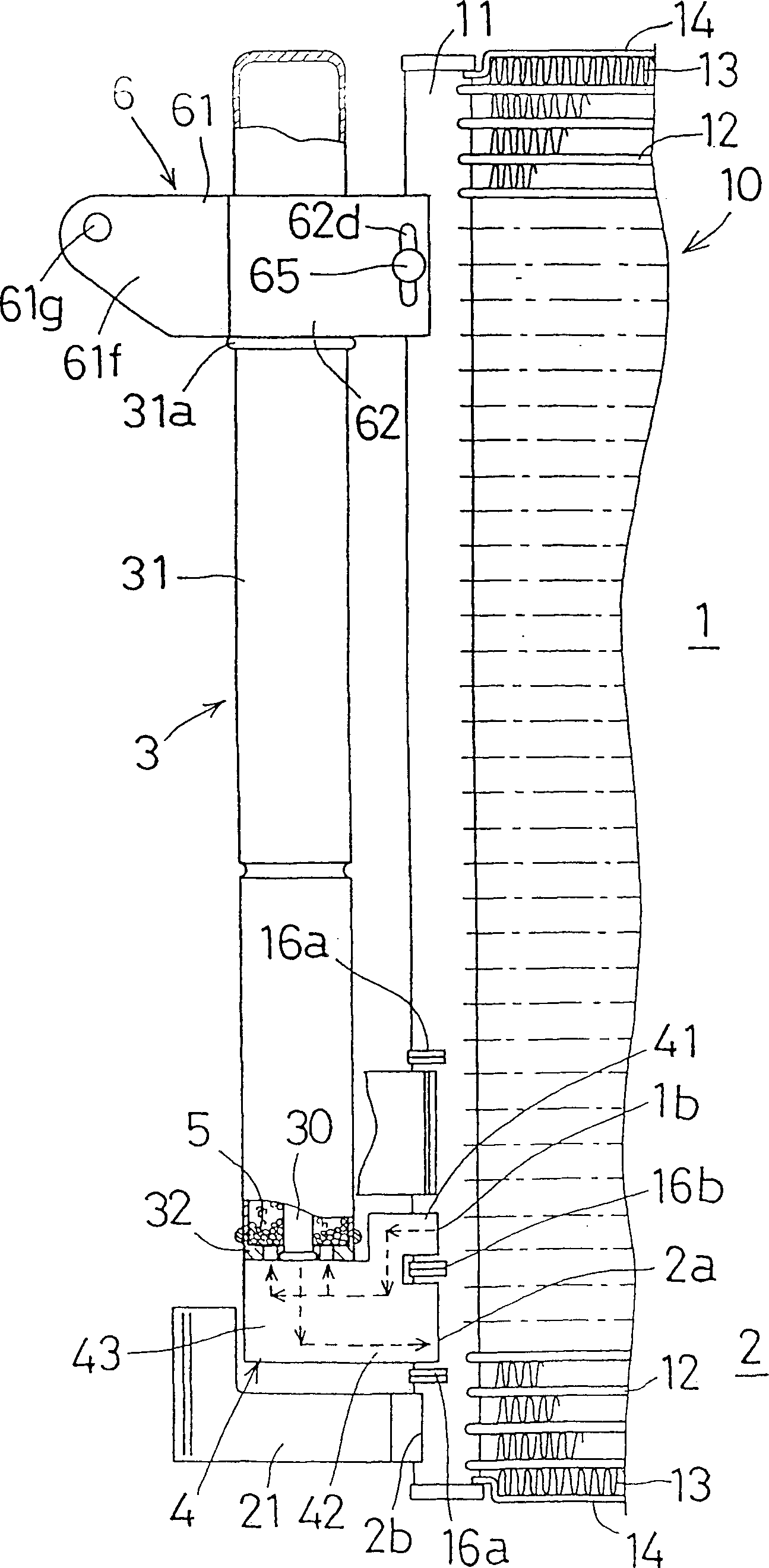
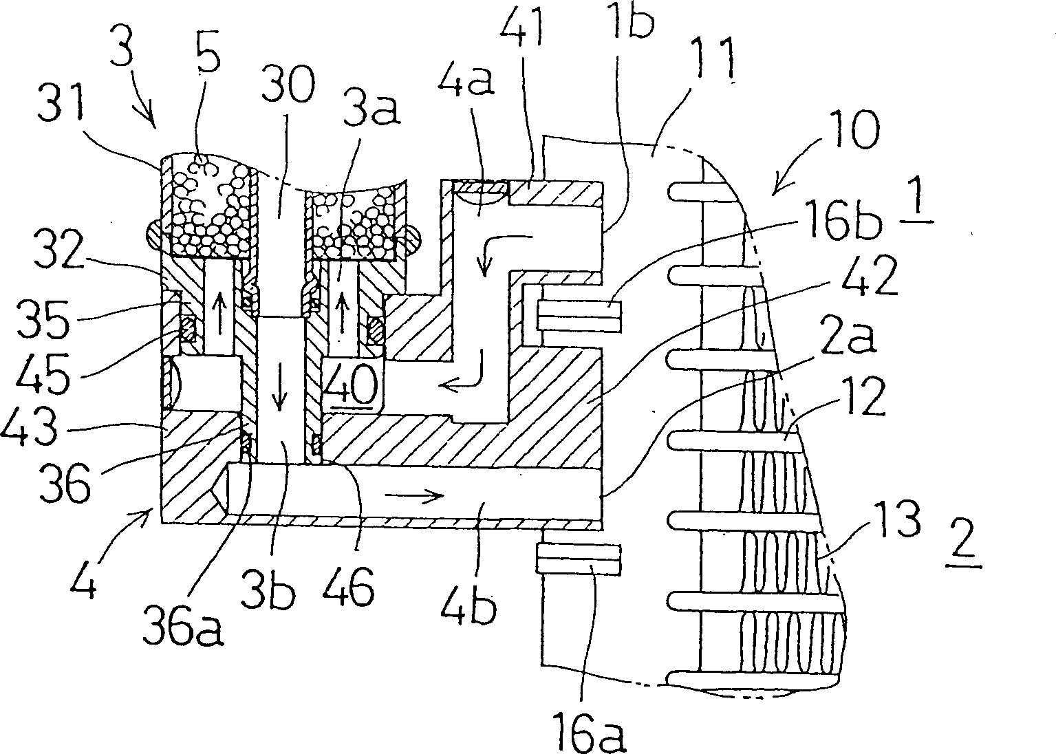
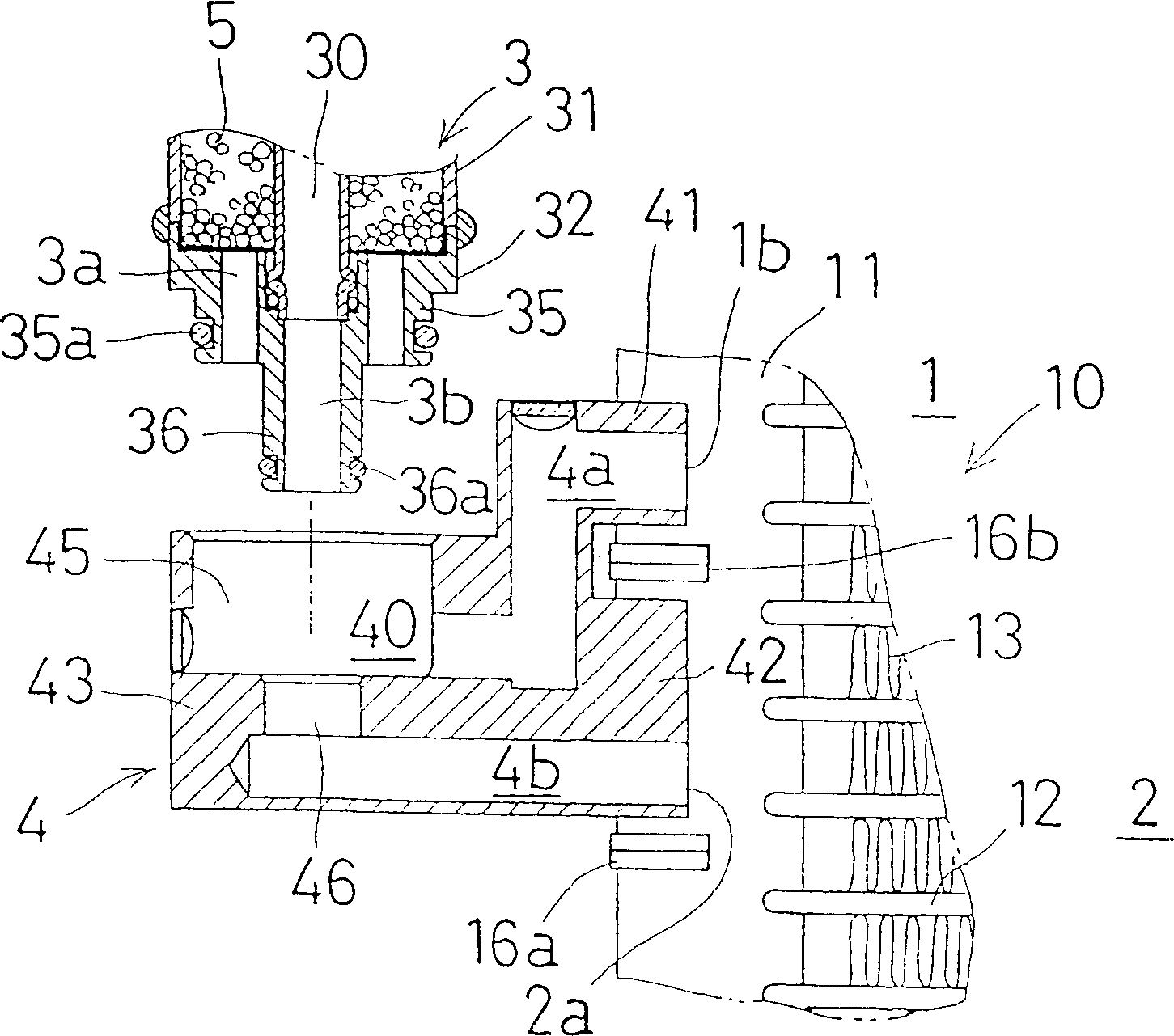
[0284] figure 1 is a front view showing one side of a heat exchanger with a liquid storage tank according to a first embodiment of the present invention, figure 2 is an enlarged partial cutaway cross-sectional view showing the block flange and its surroundings of the heat exchanger, image 3 is a partially cutaway cross-sectional view showing the block flange and its surroundings in the disassembled state.

[0285] As shown in these drawings, the heat exchanger is provided with a so-called multi-flow type heat exchanger body 10, a liquid storage tank 3, and a connecting member constituting for connecting the liquid storage tank 3 to the heat exchanger body 10 The block flange 4.

[0286] The heat exchanger body 10 is provided with a pair of left and right vertical headers 11 arranged at a certain distance. Between the pair of headers 11 are provided a plurality of horizontal flat tubes 12 as heat exchange tubes, which are arranged parallel to each other at a certain inter...

no. 2 example

[0342] Figures 15 to 18 is an enlarged view showing a block flange and its surroundings of a heat exchanger with a liquid storage tank according to a second embodiment of the present invention.

[0343] As shown in these drawings, in this heat exchanger, on both sides of the inlet of the liquid storage tank 3 and the outlet concave step portion 36 of the outlet forming member 32, a pair of laterally protruding pull-out preventing protrusions 37 are provided. and 37.

[0344] On the other hand, on the inner circumference of the outlet concave stepped portion 46 of the block flange 4, a protruding fitting slot 47b is provided in the circumferential direction thereof. In addition, on the peripheral portion of the outlet concave step portion 46 on the bottom surface of the inlet concave step portion 45, a protrusion introduction notch 47a corresponding to the above-mentioned pull-out prevention protrusion 37 and extending in the axial direction thereof is provided. The upper en...

no. 3 example

[0350] Figures 19 to 22 A heat exchanger with a liquid storage tank according to a third embodiment of the present invention is shown.

[0351] As shown in these drawings, similar to the previous embodiment, the heat exchanger is provided with a multi-flow type heat exchanger body 10, a liquid storage tank 3, and a The block flange 4 of the joining element.

[0352] In this heat exchanger body 10, an opening 1b is formed in an end portion of a partition wall 16b that divides the heat exchanger body 10 into a condensing section 1 and a recooling section 2, and this opening 1b constitutes a condensing section outlet 1b. Other structures are the same as in the foregoing embodiments.

[0353] In addition, the liquid storage tank 3 is also provided with the same structure as the previous embodiment.

[0354] For the block flange 4, on the upper surface of the block flange 4 on the side of the liquid storage tank 3, there is provided an entrance concave step whose horizontal sec...


PUM


Abstract

A heat exchanger with a receiver tank is provided with a multi-flow type heat-exchange body (10), a receiver tank (3), a block flange (4) having a side surface connected to the periphery of a condensing portion outlet of the heat exchanger body (10) and an upper end to which a lower end of the receiver tank (3) is attached and a bracket (6) for supporting the upper part of the receiver tank (3) to the heat exchanger body (10). A flange-shaped pressing stepped portion (31a) is formed on the upper periphery of the tank main body (31) of the receiver tank (3). The bracket (6) is provided with a joint portion (61b) to be secured to the peripheral surface of one of headers (11) and embracing portions (61a) and (62a) that surround the periphery of the tank main body (31) and are engaged with the upper side of the pressing stepped portion (31a) to downwardly press the receiver tank (3). With this heat exchanger, stable refrigeration performance can be obtained and that the assembling operation can be performed easily.

Description

[0001] Cross References to Related Applications [0002] This application claims priority under Section 111(b) of the United States Patent Act to Provisional Application Nos. 60 / 302646, 60 / 302657, 60 / 302690, and 60 / 302708, each filed on July 5, 2001. technical field [0003] The invention relates to a heat exchanger with a liquid storage tank suitable for automobile air-conditioning equipment, and also relates to a refrigeration system using the heat exchanger. Background technique [0004] In recent years, in a refrigerant condensation process used in a refrigeration cycle of an automobile air-conditioning system and the like, the following techniques have been proposed. In this technique, after the recooled refrigerant is obtained by increasing the heat release of the refrigerant by subcooling the condensed refrigerant to drop the temperature to several degrees below its condensing temperature, the recooled refrigerant is introduced into the Compression device and evapora...

Claims


Application Information

Patent Timeline
Patent Type & Authority Applications(China)
IPC IPC(8): F25B39/04F25B40/02F28F9/00F28F9/04
CPCF28F9/0246F25B39/04F25B40/02F25B2339/0446F28F9/002F25B2339/0441F28F9/00
Inventor 濑野善彦鸭志田理
Owner SHOWA DENKO KK
Why Eureka
Try Eureka