Raster code device and displacement measuring equipment using optical fibre receiver channel

An optical fiber receiver and grating encoder technology, applied in the field of optical encoders, can solve the problem of rough encoder accuracy, and achieve high-speed configuration, economical and configuration effects

Inactive Publication Date: 2004-05-12
MITUTOYO CORP
View PDF2 Cites 13 Cited by
  • Summary
  • Abstract
  • Description
  • Claims
  • Application Information

AI Technical Summary

Problems solved by technology

However, the accuracy of the resulting encoder is relatively coarse

Method used


Image

  • Raster code device and displacement measuring equipment using optical fibre receiver channel
  • Raster code device and displacement measuring equipment using optical fibre receiver channel
  • Raster code device and displacement measuring equipment using optical fibre receiver channel

Examples


Embodiment Construction

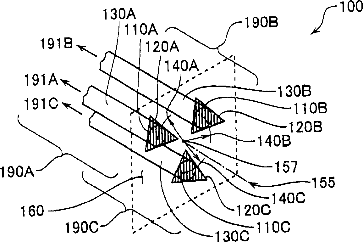
[0044] figure 1 A first general embodiment of a fiber optic receive channel arrangement 100 according to the present invention is shown. Such as figure 1 As shown, the fiber optic receiver channel configuration 100 includes three fiber optic receiver channels 190A, 190B, and 190C. Fiber optic receiver channel 190A includes a receiver channel aperture 110A, a phase mask 120A, and a receiver fiber 130A. Similarly, fiber optic receiver channel 190B includes a receiver channel aperture 110B, a phase mask 120B, and a receiver fiber 130B. Similarly, fiber optic receiver channel 190C includes a receiver channel aperture 110C, a phase mask 120C, and a receiver fiber 130C.

[0045] For each fiber optic receiver channel 190, the phase mask 230 includes a grating that completely covers the receiver channel aperture 110, which acts as a spatial filter for the incident illumination. Receiver fiber 130 is aligned with receiver channel aperture 110 such that nominally all illumination re...


PUM

PropertyMeasurementUnit
wavelengthaaaaaaaaaa
thicknessaaaaaaaaaa
widthaaaaaaaaaa

Abstract

A high accuracy miniature optical encoder is provided. A grating encoder comprises a scale (81) having a scale grating (80) formed thereon; a light source (280) operative to emit a light onto the scale grating (80); a fiber optic readhead having a tip arranged movable together with the light source (280) relative to the scale (81) along a measuring axis (82). The fiber optic readhead (300) includes a plurality of fiber optic receiver channels (190A-C) for receiving a self-image (265) formed at a certain position by the light from the scale grating (80). The fiber optic receiver channel (190) includes an optical fiber (130), a receiver channel aperture (110) formed in one end of the optical fiber, and a phase mask (120) formed at the receiver channel aperture (110). The phase mask (120) has a grating with a period corresponding to a light-and-dark period formed in the self-image. Such gratings of the fiber optic receiver channels (190A-C) have different spatial phase relationships relative to each other.

Description

technical field [0001] The present invention relates generally to displacement-sensing optical encoders, and more particularly, to an optical encoder using an optical fiber as a receiving element to provide an extremely compact and highly accurate system. Background technique [0002] A variety of motion or position encoders are currently available for sensing linear, rotational, or angular movement. These encoders are generally based either on optical systems, magnetic scales, inductive transducers, or on capacitive transducers. [0003] For optical encoders, many systems have been developed. A system was recently disclosed in US Patent No. 5,909,283 to Eselun that uses a smaller number of components than previous systems. The system disclosed in this patent has a grating scale and readhead comprising a point source (laser diode in the readhead), a Ronchi grating or holographic element, and a photodetector array. As stated, a point source of light causes interference fri...

Claims


Application Information

Patent Timeline
Patent Type & Authority Applications(China)
IPC IPC(8): G01D5/38G01D5/347G02B5/18
CPCG01D5/34723
Inventor 约瑟夫·D·托比亚松
Owner MITUTOYO CORP
Why Eureka
Try Eureka