

Washing drying machine
A technology for washing and drying machines and cabinets, which is applied to household clothes dryers, other washing machines, and washing machines with containers, etc. It can solve the problems of pipeline resonance, fatigue damage, looseness, etc., and achieve the effect of excellent durability
- Summary
- Abstract
- Description
- Claims
- Application Information
AI Technical Summary
Problems solved by technology
Method used
Image

Examples
Embodiment 1
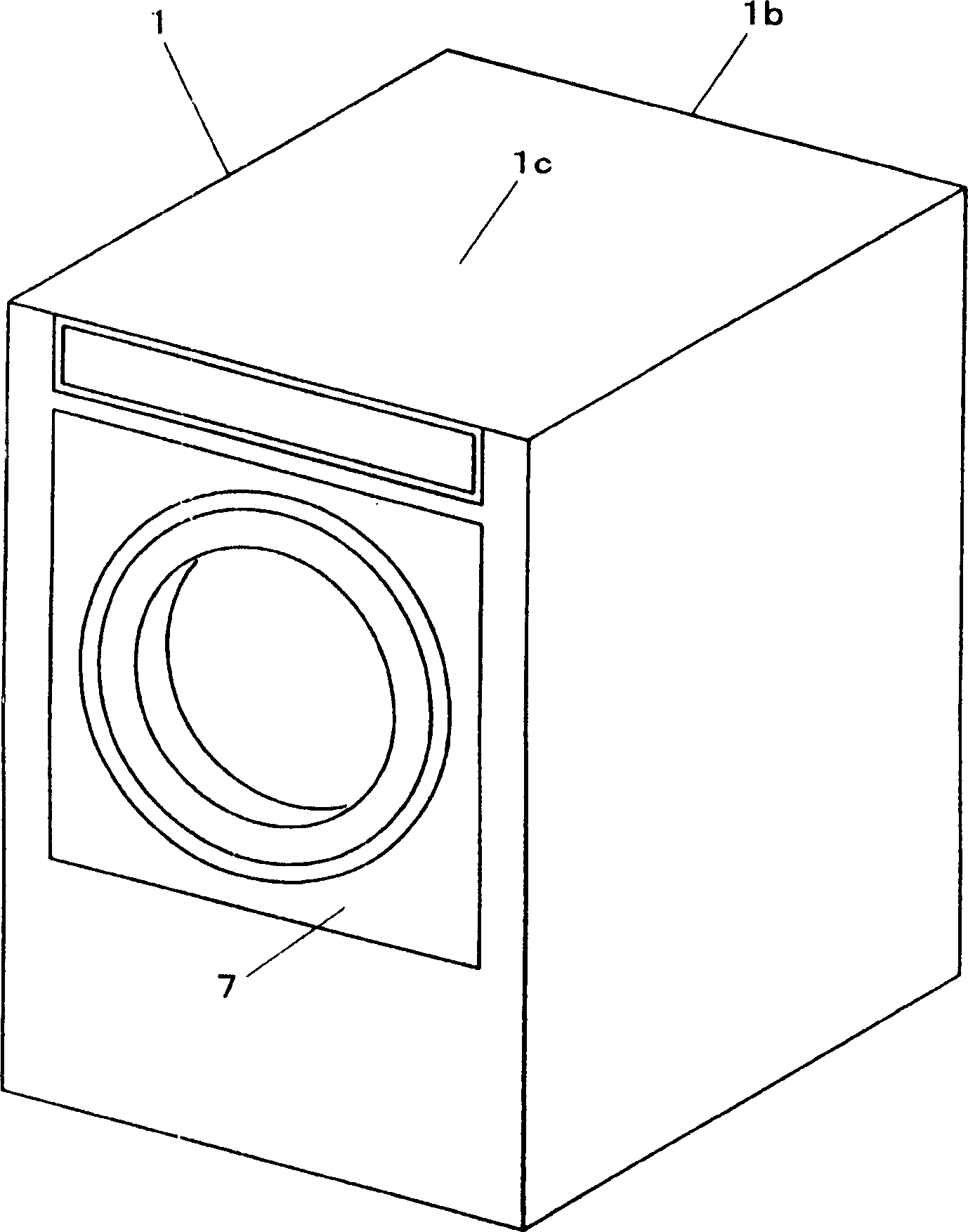
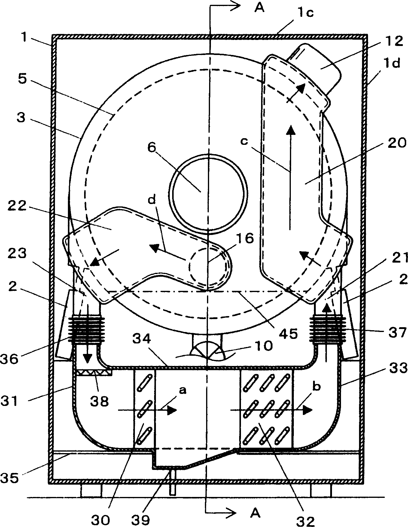
[0065] figure 1 It is a perspective view of the appearance of the washing and drying machine in the first embodiment of the present invention, figure 2 It is a cross-sectional view seen from the direction of the back side 1b of the casing 1, image 3 for along figure 2 The cross-sectional view when the A-A line is cut off, Figure 4 It is a conceptual diagram of the system showing the configuration of the heat pump device and the flow of air for drying.
[0066] As shown in these drawings, a cylindrical water bucket 3 is provided inside the cabinet 1, and the water bucket 3 is elastically supported by a plurality of shock absorbers 2, and vibrations during washing and dehydration are absorbed by the shock absorbers 2. . The inside of the water bucket 3 is provided with a freely rotatable, horizontal-axis rotating bucket 5 , which is cylindrical and used to accommodate the clothes 4 , and rotates under the drive of the driving motor 6 . On the front panel of the cabinet...
Embodiment 2
[0081] Figure 5 ~ Figure 8 2 shows the washing and drying machine shown in the second embodiment of the present invention, wherein the same components as those in the first embodiment are assigned the same symbols, and their detailed descriptions are omitted.
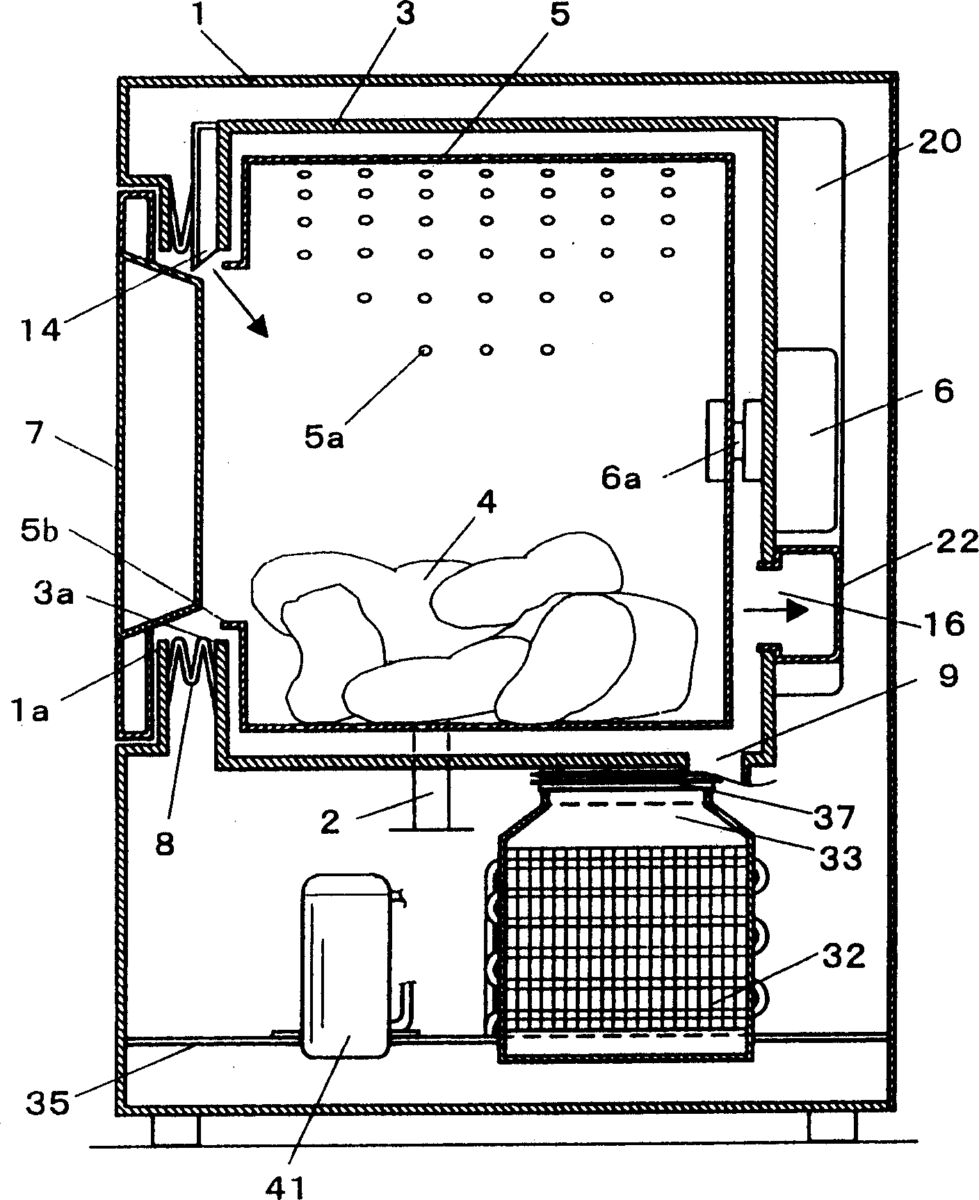
[0082] Such as Figure 5 As shown, the inside of the casing 1 is provided with: a cylindrical bucket 3 elastically supported by a plurality of shock absorbers 2; Cylindrical horizontal axis type rotating barrel 5; driving motor 6 for driving rotating barrel 5; The axis of the rotating tub 5 is tilted up at an angle of 5-45 degrees at the front relative to the horizontal direction. Correspondingly, the water bucket 3 is also inclined. In addition, the front side of the casing 1, the water bucket 3 and the rotary bucket 5 are respectively provided with openings 1a, 3a, 5b for putting in and taking out clothes etc. 4, and the opening 1a of the casing 1 is provided with an open / closed door 7. In addition, the opening ...
Embodiment 3
[0092] Figure 9 It is a cross-sectional view of the washer-dryer in the third embodiment of the present invention seen from the rear direction, wherein the same components as those in the first embodiment are assigned the same symbols, and their detailed descriptions are omitted.
[0093] In this embodiment, the heat pump device is arranged above the water tub 3 . Such as Figure 9 As shown in the figure, the upper part of the bucket 3 is provided with: a heat absorber 30 constituting an integral part of the heat pump device; a heat absorber air duct 31; a heat radiator 32; a heat radiator air duct 33; A compressor 41 , a throttling device 42 and a (refrigerant) line 43 are shown.
[0094] The inlet of the heat absorber air duct 31 is communicated with the outlet of the exhaust duct 23 by an exhaust port hose 36 made of a bellows-shaped flexible flexible material. Similarly, the outlet and the inlet of the radiator air duct 33 The inlets 21 of the air ducts are also commun...
PUM
 Abstract
Description
Claims
Application Information