Supercharge Your Innovation With Domain-Expert AI Agents!

Plastic-flow connector and its connecting method

一种塑性流动、结合体的技术,应用在电动组件、刚性轴联轴器、制造电动发电机等方向,能够解决成本变高、高零件精度、易产生摩擦或咬住等问题

Inactive Publication Date: 2004-05-19
HITACHI LTD
View PDF2 Cites 7 Cited by
  • Summary
  • Abstract
  • Description
  • Claims
  • Application Information

AI Technical Summary

Problems solved by technology

[0008] In the bonding method described in the above-mentioned Patent Document 1, since the plastic flow bonding is performed after the two members are fitted with a clearance fit, the other portions except for the vicinity of the portion that was pressed and plastically flowed become strictly gaps. , the bonding strength is weak especially for bending, and it becomes a problem especially when the thin plate members are pushed to make plastic flow for bonding
[0009] In addition, in the bonding method described in Patent Document 2, since the plastic flow bonding is performed after the two members are press-fitted, although there is no gap in the vicinity of the pressed and plastic-flowed part, the bonding strength is especially for The bonding strength of bending is strong, but when press-fitting, it is easy to cause friction or bite on the two members, and bending or contamination due to press-fitting occurs (Contami)
In addition, in order to manage the press-fit allowance, high part accuracy is required, which increases the cost

Method used


Image

  • Plastic-flow connector and its connecting method
  • Plastic-flow connector and its connecting method
  • Plastic-flow connector and its connecting method

Examples


Embodiment Construction

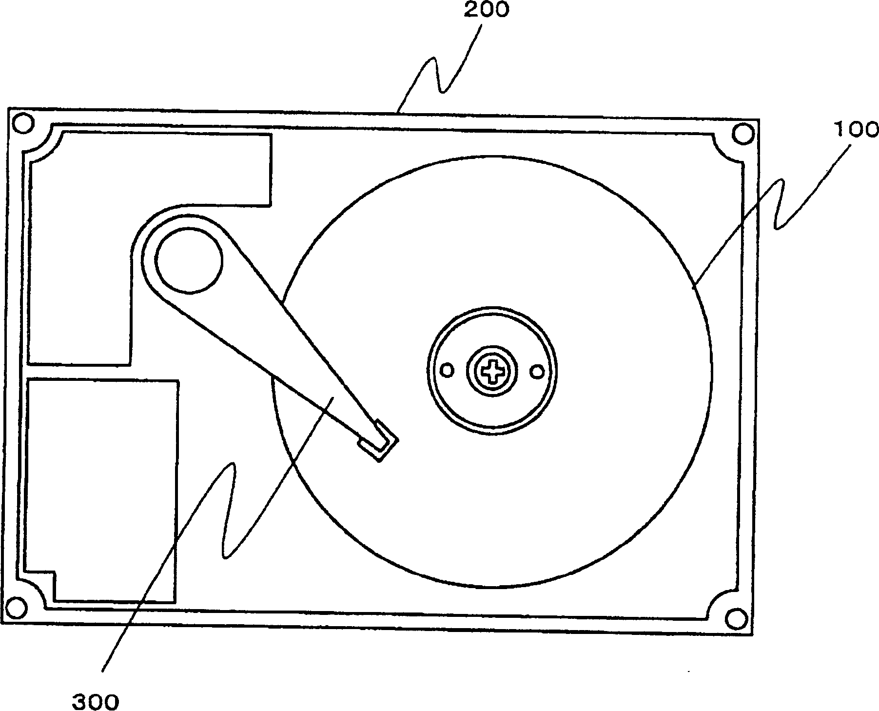
[0029] The present invention is a combination method and a combination, the combination method and the combination are plastic flow bonding spindle motors used in disk devices such as electronic computers, DVDs, and CD-ROMs, especially portable devices such as notebook personal computers. A method and combination of two components such as the shaft and the hub of a spindle motor with a dynamic pressure bearing structure in a thin hard disk drive motor mounted on a computer. As an embodiment of the bonding method and the bonded body of the present invention, a dynamic pressure bearing spindle motor of a hard disk device using a hub and a shaft bonded body will be described as an example.

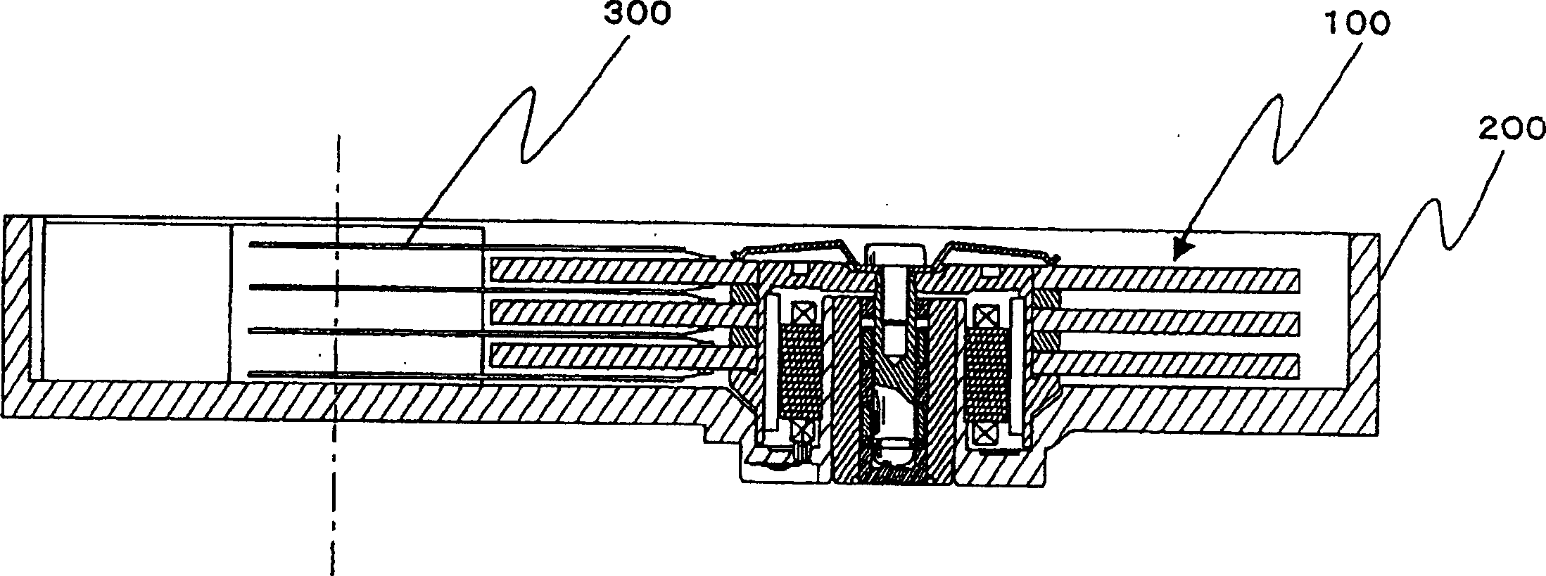
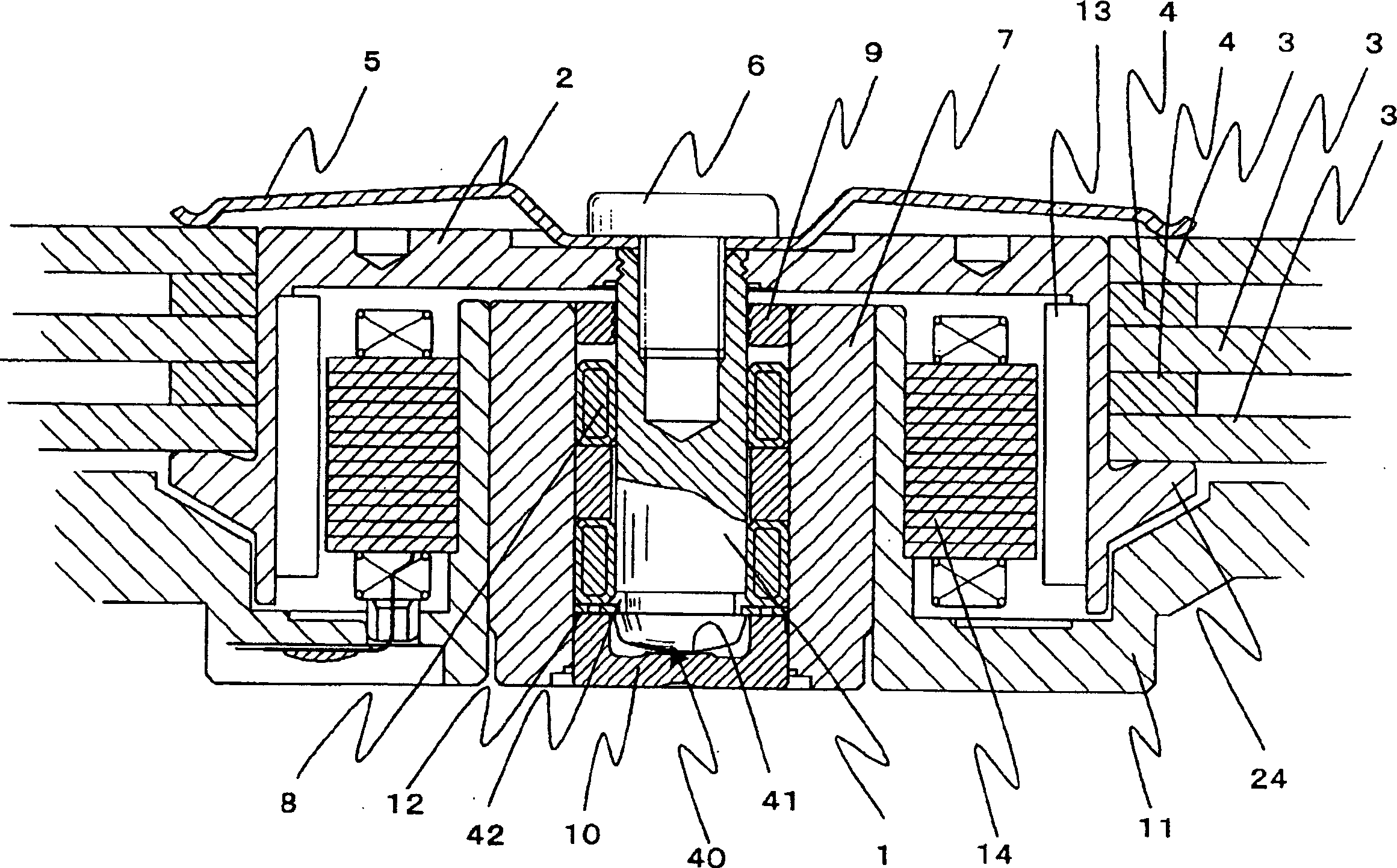
[0030] exist figure 1 , shows the overall view of the hard disk device, in figure 2 Expressed in figure 1 A cross-sectional view of the hard disk unit shown.

[0031] exist figure 1 and figure 2 Among them, 200 is a hard disk device (HDD). In this hard disk device (HDD) 200, the dyn...


PUM


Abstract

The disclosure is concerned with a bonding method for bonding metallic members, which comprises the steps of: fitting a metallic members to another metallic member, followed by effecting preliminarily plastic bonding by means of a preliminarily bonding punch; and generating compression force in an axial direction of the members in the vicinity of the fitting portion of the bonding members after the preliminarily plastic bonding, and allowing part of the material of the bonding member to effect plastic-flow in such a manner as to fill a gap defined between the metallic members, so as to plastically bond the members; whereby the members are tightly integrated with each other.

Description

technical field [0001] The invention relates to a combination method and combination body for combining two components by plastic flow. Background technique [0002] A conventional method of fitting and plastic-flow joining two members employs a method of plastic-flow joining the two members in a state of clearance fit (for example, refer to Patent Document 1). [0003] In addition, a conventional method of fitting and plastic-flow joining two members uses a method of press-fitting and plastic-flow joining two members (for example, refer to Patent Document 2). [0004] 【Patent Document 1】 [0005] Japanese Patent Application Laid-Open No. 11-120743 (page 4, image 3 , Figure 4 ) [0006] 【Patent Document 2】 [0007] Japanese Patent Laid-Open No. 2001-54268 (page 2, figure 1 ) [0008] In the bonding method described in the above-mentioned Patent Document 1, since the plastic flow bonding is performed after the two members are fitted with a clearance fit, the other po...

Claims


Application Information

Patent Timeline
Patent Type & Authority Applications(China)
IPC IPC(8): B21D39/00B21K25/00B23P11/00F16D1/072G11B19/20H02K7/00H02K15/03
CPCY10T29/49938Y10T403/49B21K25/00F16D1/072G11B19/2009B23P11/00H02K7/003Y10T29/49012H02K15/03
Inventor 原田幸治
Owner HITACHI LTD
Features
  • R&D
  • Intellectual Property
  • Life Sciences
  • Materials
  • Tech Scout
  • Unparalleled Data Quality
  • Higher Quality Content
  • 60% Fewer Hallucinations
Learn More