Base station apparatus, communication terminal apparatus, and radio communication method

A technology for communication terminals and base stations, which is applied to wireless communication, communication between multiple stations, and devices dedicated to transmitters, etc., and can solve problems such as inability to grasp the propagation path.

Inactive Publication Date: 2004-05-19
PANASONIC CORP
View PDF0 Cites 9 Cited by
  • Summary
  • Abstract
  • Description
  • Claims
  • Application Information

AI Technical Summary

Problems solved by technology

Therefore, this causes a problem that the communication device cannot grasp the change of the propagation path due to its moving speed, etc., which causes the base station device to determine a non-optimum transmission system for the communication terminal device based on the reported radio quality
However, this communication terminal device cannot grasp changes in radio quality on a real-time basis during the time of slow movement

Method used


Image

  • Base station apparatus, communication terminal apparatus, and radio communication method
  • Base station apparatus, communication terminal apparatus, and radio communication method
  • Base station apparatus, communication terminal apparatus, and radio communication method

Examples


Embodiment 1

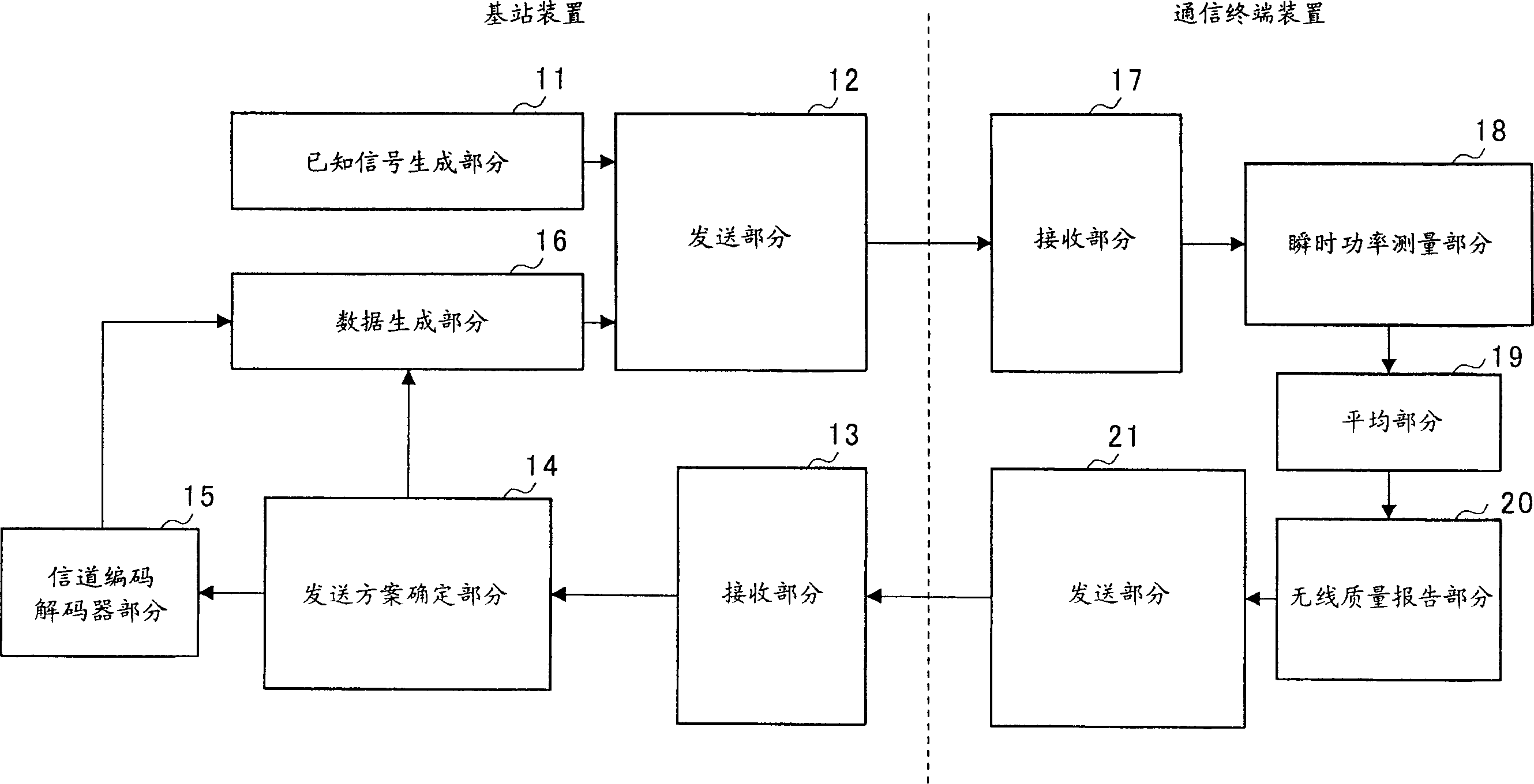
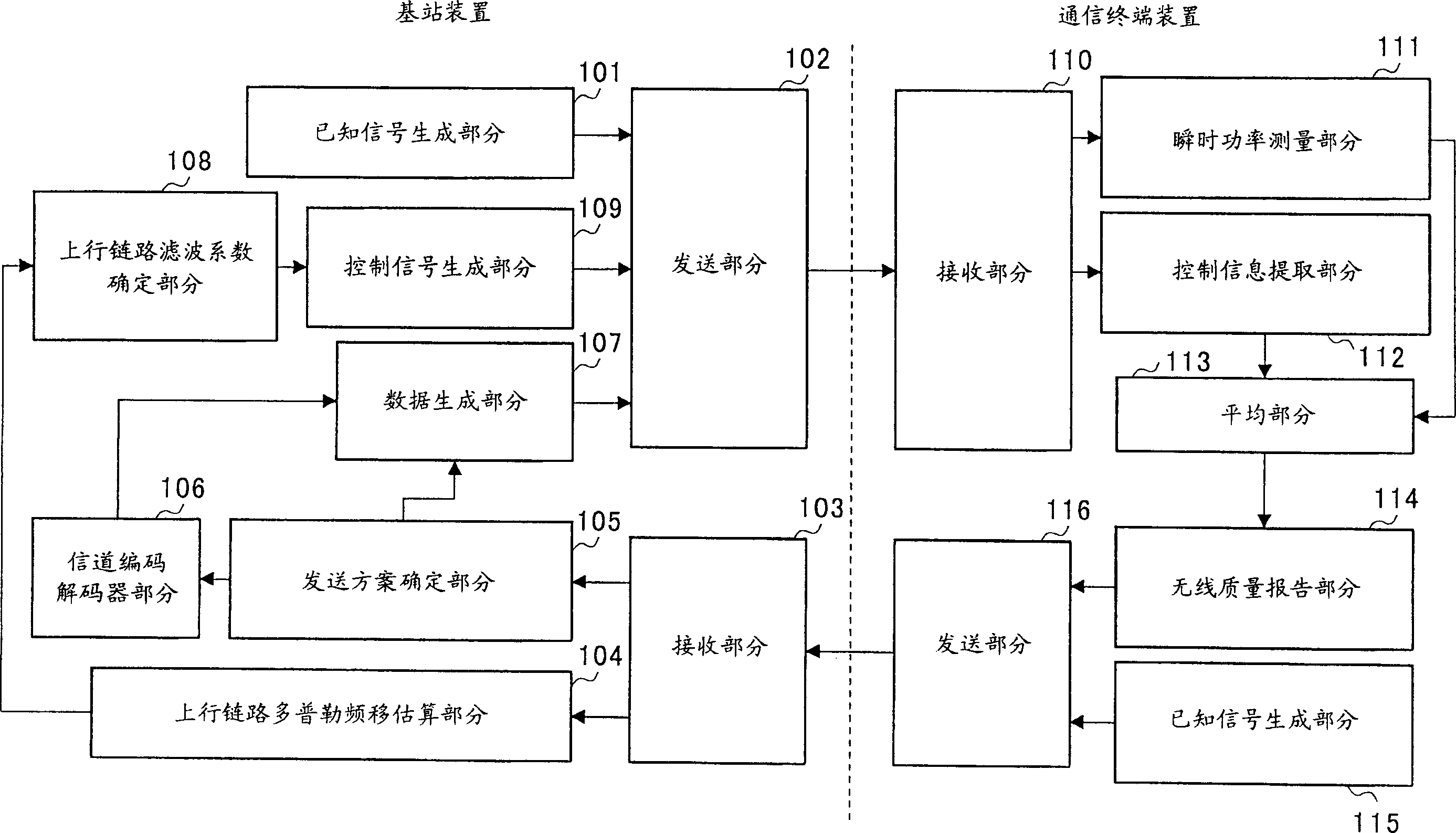
[0032] figure 2 Is a block diagram showing the configuration of the wireless communication system according to the first embodiment of the present invention.

[0033] First refer to the attached figure 2 The base station apparatus according to the present invention will be explained. in figure 2 Among them, the base station apparatus includes a known signal generation section 101, a transmission section 102, a reception section 103, an uplink Doppler shift estimation section 104, a transmission scheme determination section 105, a channel codec section 106, a data generation section 107, The uplink filter coefficient determination section 108 and the control signal generation section 109.

[0034] The known signal generating section 101 generates a known signal (reference signal) known to the communication terminal device, and the transmitting section 102 performs wireless processing on the known signal, a control signal, and other signals (transmission data) to remove the proc...

Embodiment 2

[0053] Figure 4 Is a block diagram showing the configuration of a wireless communication system according to the second embodiment of the present invention. in Figure 4 In, right and in figure 2 Identical or equivalent components in the, are assigned the same reference numerals, and detailed descriptions thereof are omitted. Here, a description will be given of a part particularly related to the second embodiment.

[0054] Such as Figure 4 As shown, in this second embodiment, a downlink Doppler frequency shift estimation part 301 and a downlink filter coefficient determination part 302 are provided for the system instead of figure 2 The uplink Doppler shift estimation section 104 and the uplink filter coefficient determination section 108 and the control signal generation section 109 are shown in.

[0055] In the communication terminal device, the downlink Doppler shift estimation section 301 estimates the Doppler shift amount of the received known signal, and the downlink f...

Embodiment 3

[0062] Figure 5 Is a block diagram showing the configuration of a wireless communication system according to the third embodiment of the present invention. in Figure 5 In the right and in figure 2 Identical or equivalent components in the, are assigned the same reference numerals, and detailed descriptions thereof are omitted. Here, a description will be given of a part particularly related to the third embodiment.

[0063] Such as Figure 5 As shown, in this third embodiment, an uplink report power selection part 401 and a downlink report power switching part 402 are provided for the system instead of figure 2 The uplink filter coefficient determination section 108 shown in.

[0064] In the base station device, based on the amount of Doppler shift estimated in the uplink Doppler shift estimation section 104, the uplink report power selection section 401 selects one for obtaining the radio quality reported by the communication terminal device The power value of the value.

[...


PUM


Abstract

In a base station apparatus, an upstream Doppler shift estimating part (104) estimates the Doppler shift amount of a received signal, an upstream filter factor deciding part (108) decides a filter factor from the Doppler shift amount, and a control signal producing part (109) produces and transmits a control signal indicative of the filter factor to a communication terminal apparatus. In the communication terminal apparatus, a control information extracting part (112) extracts the filter factor from the control signal, and an averaging part (113) averages, in a time period based on the filter factor, instantaneous power values determined by an instantaneous power measuring part (111) and calculates a noise power value. A radio quality informing part (114) transmits to the base station apparatus a signal indicative of a radio quality based on the averaged power value and noise power value. In the base station apparatus, a transmission method deciding part (105) decides, based on the radio quality, a modulation scheme and a coding rate. In this way, the reliability of the radio quality informed to the base station apparatus can be raised and the modulation scheme decided based on the radio quality can be optimized.

Description

Technical field [0001] The present invention relates to a base station device, a communication terminal device and a wireless communication method. Background technique [0002] The adaptive modulation scheme is a scheme that changes the modulation signal and data transmission rate according to the conditions of the propagation path of the communication terminal device. In such an adaptive modulation scheme, a communication terminal device with good propagation path conditions transmits signals at a high transmission rate. On the other hand, communication terminal devices with poor propagation path conditions transmit signals at a low transmission rate. This improves the throughput of the wireless communication system as a whole. [0003] In a wireless communication system using a conventional adaptive modulation scheme, the communication terminal device measures the quality of wireless transmission using a known signal transmitted from the base station device, and the base stati...

Claims


Application Information

Patent Timeline
Patent Type & Authority Applications(China)
IPC IPC(8): H04B7/26H04B17/24H04B17/309H04B17/318H04L1/00H04W28/18H04W88/02H04W92/10
CPCH04L1/0034H04L1/0009H04L1/0003H04L1/0026H04L1/0015H04W24/10H04W88/08
Inventor 筱井健一郎
Owner PANASONIC CORP
Why Eureka
Try Eureka