
Safety device of automatic machinery system

By configuring a detection device in the automatic machinery system to determine and stop the automatic machinery, the safety hazard problem of operators entering the working area is solved, efficient operator supply and equipment operation are achieved, and costs and downtime are reduced.

Inactive Publication Date: 2004-05-26
FANUC LTD
View PDF1 Cites 9 Cited by
  • Summary
  • Abstract
  • Description
  • Claims
  • Application Information

AI Technical Summary

Problems solved by technology

However, in this method, the operation needs to be stopped frequently in order to supply the object to be processed, which is inefficient.
In addition, although it is possible to use the turntable and the slide plate instead of the operator to supply the object to be processed to each work area, there is a problem that additional equipment such as the turntable, the slide plate and its control are required

Method used


Image

  • Safety device of automatic machinery system
  • Safety device of automatic machinery system
  • Safety device of automatic machinery system

Examples


Embodiment Construction

[0014] The above and other objects and features of the present invention can be more clearly understood through the following description of the embodiments with reference to the accompanying drawings.

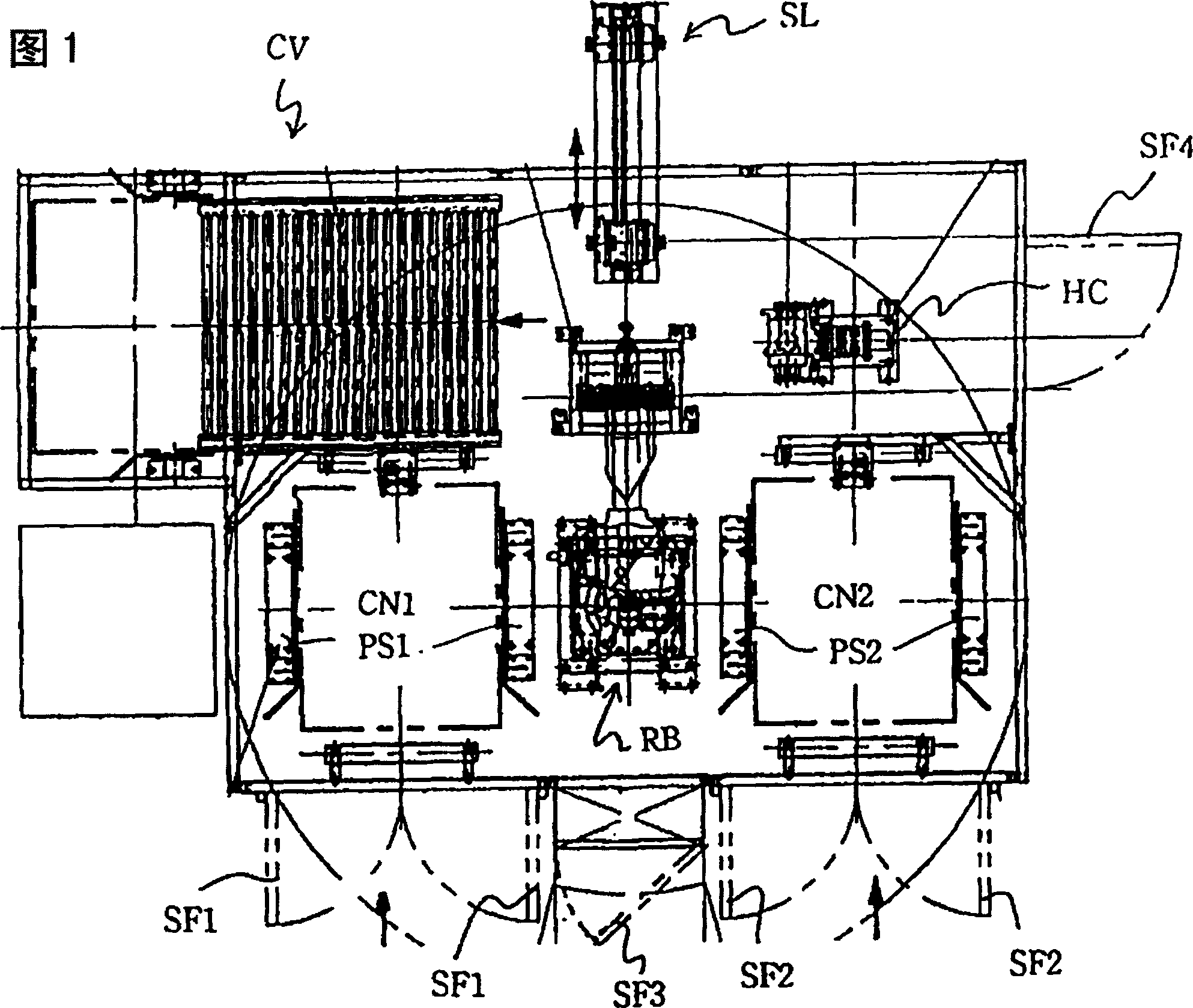
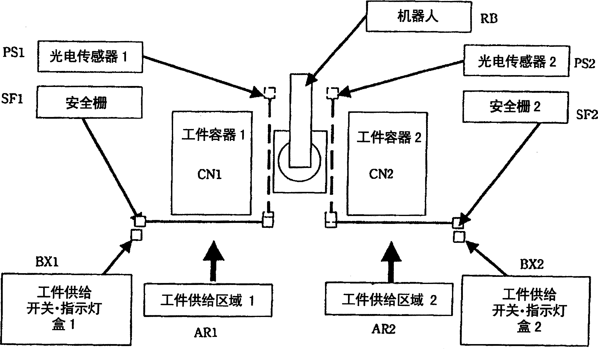
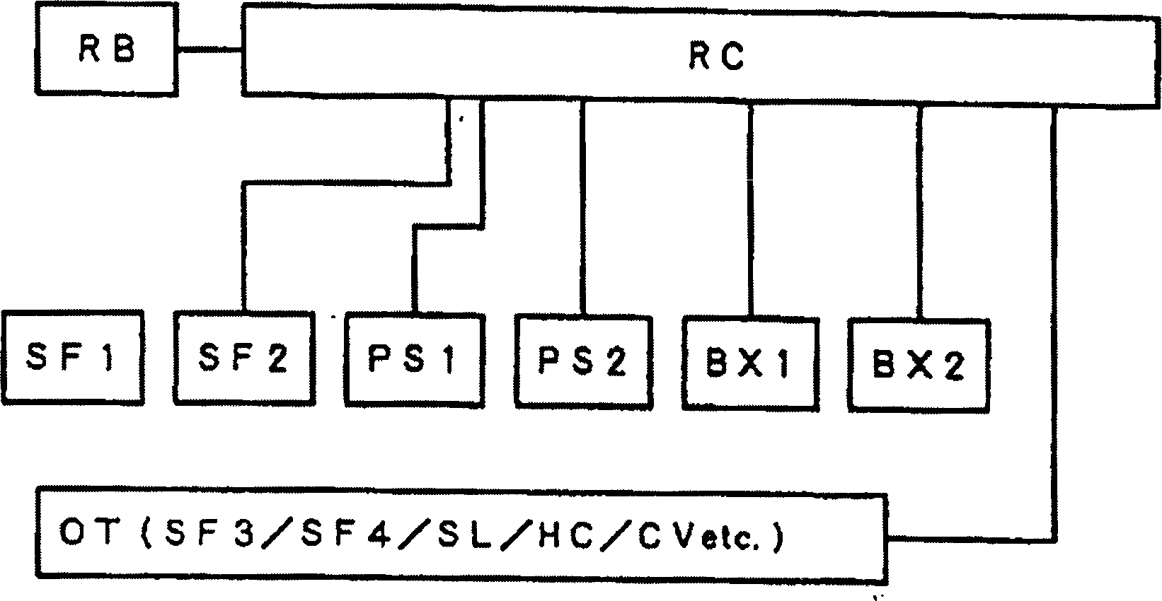
[0015] FIG. 1 is a schematic diagram showing an overall layout of a robot system to which a safety device according to an embodiment of the present invention is applied. figure 2 It is a block diagram that extracts the parts related to the present invention from the general arrangement shown in FIG. 1 and briefly describes them. in addition, image 3 It is a diagram showing the connection relationship between each part of the system and the control device (robot controller) of the system. The present embodiment will be described below with reference to these figures. In addition, although in this embodiment, the automatic machine is used as a robot, and the operation is described as holding and conveying the workpiece, it may also be other automatic machines that perform oth...


PUM


Abstract

During a robot taking workpieces out of a workpiece container 2, a safety fence 2 and a photoelectric sensor 1 are valid and the robot is stopped when the safety fence 2 is opened or a beam from the photoelectric sensor 1 is cut off. A safety fence 1 and a photoelectric sensor 2 are invalid and do not hinder operation of the robot. Operation feasible state indicating lamps of workpiece feeding lamp / switch boxes 1 and 2 are turned on and off, respectively. If an operator replaces a workpiece container 1, he / she actuates an operating area entrance switch or the box 1 into an ON state to make OFF state an operation feasible signal for the robot RB on a side of the workpiece container 1. When the robot is operating on the side of the workpiece container 1, the robot can continue to operate while similarly ensuring safety of the operator.

Description

technical field [0001] The present invention relates to an automatic machine configured such that an operator supplies an object to be processed from a preparation area adjacent to each operation area to each operation area while using an automatic machine such as a robot to perform operations on the object to be processed in several operation areas. A safety device in the system to ensure the safety of the operator. Background technique [0002] When an automatic machine such as a robot is used to work on an object to be processed, in many cases the system is configured such that a working area for the automatic machine is set up near the automatic machine, and processing is prepared in advance in a preparation area adjacent to the working area. Object, from which the operator supplies the object to be processed to each work area. In such a system, of course, the operator needs to be careful not to enter the work area where the robot is working, but sometimes accidentally ...

Claims


Application Information

Patent Timeline
Patent Type & Authority Applications(China)
IPC IPC(8): B25J19/06F16P3/08F16P3/14G05B19/18
CPCB25J19/06F16P3/144F16P3/08F16P3/14
Inventor 渡边淳小田胜
Owner FANUC LTD
Learn More