Driving method and driver for active luminous display panel

A technology of light-emitting display and driving method, which is applied in the direction of lighting devices, electroluminescent light sources, light sources, etc., and can solve the problems of poor linearity of gray scale control, decreased luminous efficiency, and reduced lighting time rate of EL elements, etc.

Inactive Publication Date: 2004-05-26
TOHOKU PIONEER CORP
View PDF1 Cites 34 Cited by
  • Summary
  • Abstract
  • Description
  • Claims
  • Application Information

AI Technical Summary

Problems solved by technology

Therefore, even if a driving voltage is applied to the EL element in the forward direction, electric charges are charged in the above-mentioned parasitic capacitance, and a predetermined time is required to reach the emission threshold voltage.
In addition, as mentioned above, due to the relationship of constant current driving, the impedance is substantially high, and it takes time to rise to the emission threshold voltage of the above-mentioned EL element.
[0013] In addition, as described above, when the method of applying a reverse bias voltage to the EL element is used, since charges are accumulated in the above-mentioned parasitic capacitance of the EL element in the reverse bias state, when the forward voltage is applied, It will take time for the EL element to reach the light-emitting state
Therefore, the lighting time rate of the EL element is lowered, and the luminous efficiency is substantially lowered.
In addition, each EL element is affected by the dispersion of the time to reach the light-emitting state, etc., and there is a problem that the linearity of the gradation control is deteriorated.

Method used


Image

  • Driving method and driver for active luminous display panel
  • Driving method and driver for active luminous display panel
  • Driving method and driver for active luminous display panel

Examples


Embodiment Construction

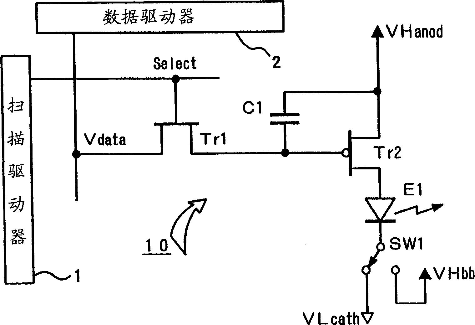
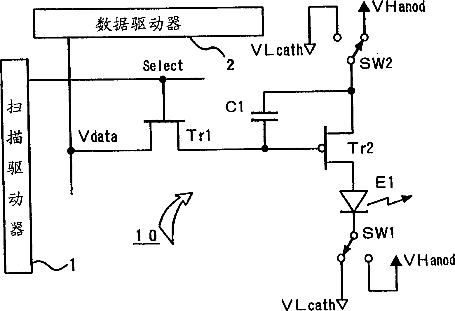
[0042] Hereinafter, the drive device for a light-emitting display panel of the present invention is divided into first to fifth aspects, and their respective features will now be described. First, the first aspect of the driving device of the present invention is characterized in that the parasitic capacitance accumulated in the above-mentioned light-emitting element is reduced by setting the anode and cathode of the light-emitting element at the same potential when the light-emitting element shifts to the lighting operation. The discharge work in which the charge is discharged.

[0043] Then, in the first embodiment of the first aspect of the driving device of the present invention, as figure 2 As shown, the first and second switching switches SW1 and SW2 are provided, and by switching the switches SW1 and SW2, it is applied to an example configured to switch the connection relationship between the anode side power supply (VHanod) and the cathode side power supply (VLcath). ...


PUM


Abstract

In a drive device for an active type light emitting display panel which can apply a reverse bias voltage to an EL element, in order to be able to compensate deterioration in light-emitting efficiency of the EL element accompanied by applying of the reverse bias voltage and the like, one pixel 10 is composed of a controlling TFT (Tr1), the driving TFT (Tr2 ) , a capacitor C1, and the EL element E1. Switching switches SW1, SW2 mutually enables a supplying state of a forward current to the EL element E1 and an applying state of the reverse bias voltage to be selected . In one control form according to the present invention, when the applying state of the reverse bias voltage shifts to the supplying state of the forward current, by switching one switch first, the anode and cathode of the EL element E1 are made to the same electrical potential to allow electrical charges to be discharged. Thus, charge of the forward current for a parasitic capacitance of the EL element E1 can be performed rapidly, and rising of the lighting operation of the EL element can be advanced.

Description

technical field [0001] The present invention relates to a driving device for a light-emitting display panel that can apply a reverse bias voltage to the above-mentioned light-emitting element while actively driving the light-emitting element constituting a pixel with a TFT (Thin Film Transistor), especially capable of compensating the luminous efficiency of the above-mentioned light-emitting element A driving method and a driving device of an active light-emitting display panel that decreases with the application of a reverse bias voltage. Background technique [0002] The development of a display using a display panel configured by arranging light-emitting elements in a matrix is ​​progressing widely. As a light-emitting element used in such a display panel, an organic EL (electroluminescence) element in which an organic material is used for a light-emitting layer is attracting attention. This is because, as a background, progress has been made in improving efficiency and ...

Claims


Application Information

Patent Timeline
Patent Type & Authority Applications(China)
IPC IPC(8): H01L51/50G09G3/10G09G3/20G09G3/30G09G3/32H05B33/14
CPCG09G2300/0852G09G2300/0842G09G2320/043G09G2300/0809G09G3/3241G09G3/325G09G2320/0252G09G2300/0866G09G3/3233G09G2300/0819G09G2310/0254G09G2310/0256G09G3/30
Inventor 吉田孝义金内一浩
Owner TOHOKU PIONEER CORP
Why Eureka
Try Eureka