Air supply apparatus for air jet loom

A technology of air supply and air injection, applied in looms, textiles, textiles and papermaking, etc., can solve the problems of complicated air supply device, electrical failure of control system, increase of injection pressure loss, etc., to achieve simplification and reduction Effect of using quantity and reducing quantity

Inactive Publication Date: 2004-06-02
TSUDAKOMA KOGYO KK
View PDF1 Cites 11 Cited by
  • Summary
  • Abstract
  • Description
  • Claims
  • Application Information

AI Technical Summary

Problems solved by technology

[0005] Therefore, as the number of main nozzles increases, it is necessary to increase the installation space of the on-off valve, and the number of pipes connected to the on-off valve, the compressed air regulator, and the main nozzle also increases, making the inside of the air supply device complicated, and Make the control of the on-off valve very complicated
[0006] In addition, when there are many or long pipes, the injection pressure loss will also increase accordingly. If there are more on-off valves, there may be more electrical failures in the control system, which often makes weft insertion unstable.

Method used


Image

  • Air supply apparatus for air jet loom
  • Air supply apparatus for air jet loom
  • Air supply apparatus for air jet loom

Examples


no. 1 Embodiment

[0039] [Example 1: Air supply device for monochrome loom]

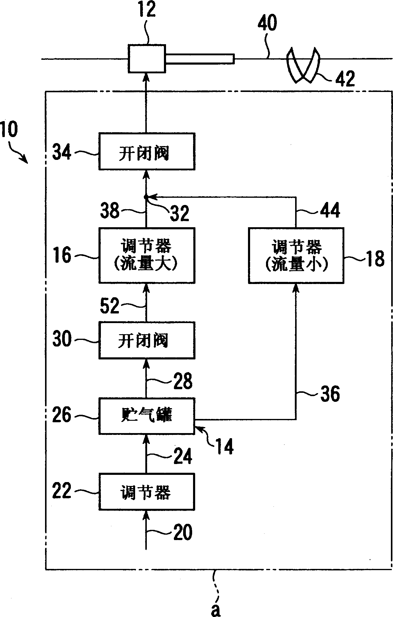
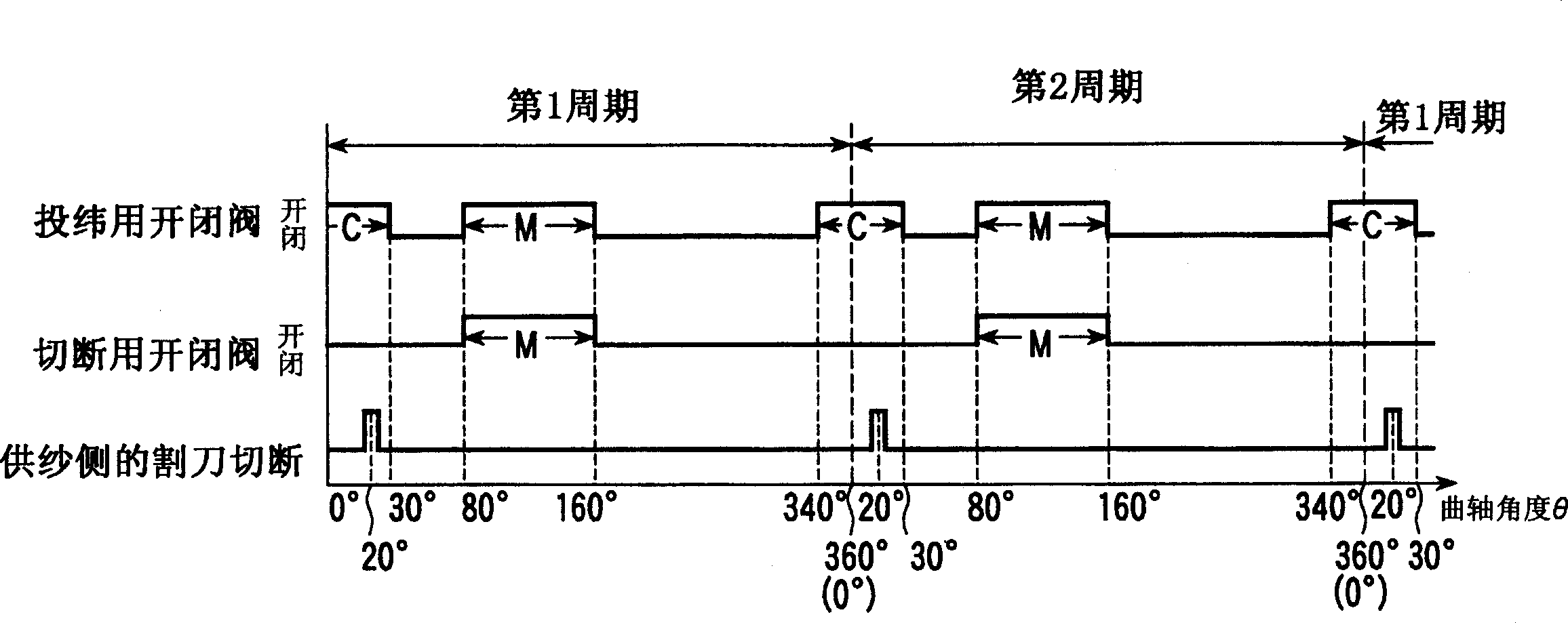
[0040] refer to figure 1 and figure 2 , the air supply device 10 is used for a monochrome loom having one main nozzle 12 .

[0041] The air supply device 10 has a piping circuit a in which compressed air regulators 16 and 18 for weft insertion and cutting are connected in parallel between the compressed air supply source 14 and the main nozzle 12 .

[0042] The compressed air supply source 14 includes: a pressure source (not shown) such as a compressor; an auxiliary compressed air regulator (hereinafter simply referred to as "regulator") 22 connected to the air outlet of the pressure source through a piping 20; A compressed air tank (hereinafter simply referred to as “air tank”) 26 connected to the air outlet of the regulator 22 through a pipe 24 .

[0043] The pipe 28 protruding from one air outlet of the air tank 26 goes from the air tank 26 to the downstream side, passes through the on-off valve 30, the compres...

no. 2 Embodiment

[0055] [Second embodiment: Air supply device for two-color loom]

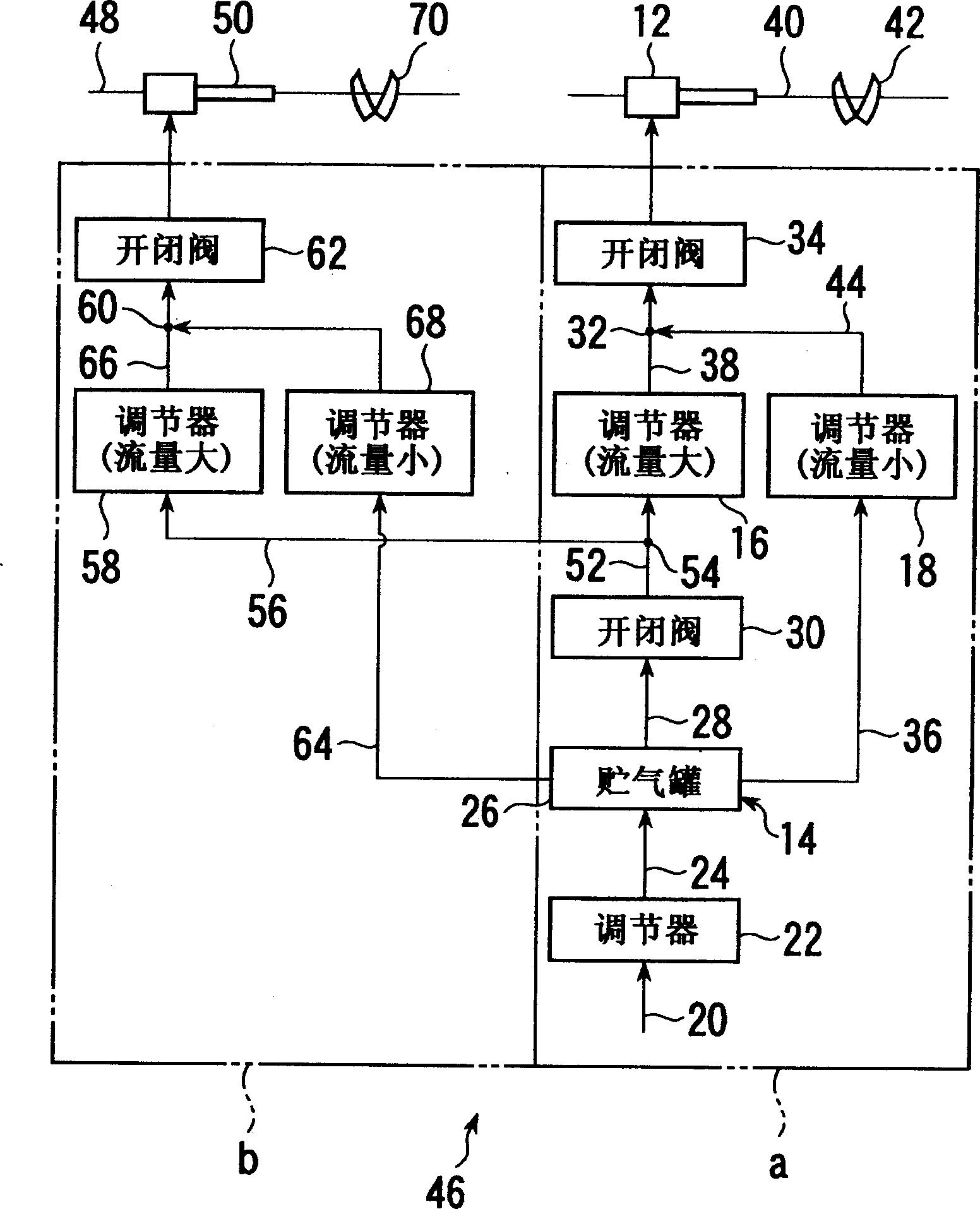
[0056] Please refer to image 3 and Figure 4 In addition to the piping path a in the air supplying device 10, the air supply device 46 also uses a piping circuit equipped with a piping path b that connects the compressed air supply source 14 with the main nozzle 50 that makes other weft yarns 48 fly away, Also, this air supply device 46 is used for a two-color loom.

[0057] The piping line b has a branch line 54 on the piping 52 between the on-off valve 30 and the compressed air regulator 16 . The distribution pipe 56 protruding from the branch path 54 is connected downstream from the branch path 54 to the main nozzle 50 through a compressed air regulator 58 , a confluence path 60 , and an on-off valve 62 in this order. A pipeline 64 extending from the third air outlet of the air tank 14 is connected to a confluence path 60 arranged on a pipe 66 extending from the compressed air regulator 58 through a comp...

no. 3 Embodiment

[0073] [Third embodiment: Air supply device for two-color loom]

[0074] Please refer to Figure 5 In addition to the piping path a in the air supplying device 10, the air supplying device 72 also uses a piping circuit having a piping path b connected to the main nozzle 50 for flying the weft yarn 48, and the air supplying device 72 Can be used on two-color looms.

[0075] The air supply device 72 connects the pipeline 74 that acts as a branch pipeline with the figure 1 The merged passage 32 of the shown air supply device 10 is connected, the merged passage 32 is used as a merged branch passage 76 , and the pipe 74 is connected to the main nozzle 50 through the on-off valve 62 . However, the air supply device 72 may connect the pipe 74 serving as a branch pipe to the pipe extending from the confluence passage 32 of the air supply device 10 to the main nozzle 12, thereby connecting the confluence passage 32 and the vicinity of the pipe 74 Make a confluence branch road 76 . ...


PUM


Abstract

To simplify piping from a compressed air feed source to a main nozzle. The air feeder comprises a first opening and closing valve connected to the compressed air feed source, one or more first compressed air conditioners connected to the first opening and closing valve and setting the amount of flow or the pressure to a prescribed first set value, one or more second compressed air conditioners connected to the compressed air feed source and setting the amount of flow or the pressure to a second set value and having the number equivalent to or larger than the number of the first compressed air conditioners and one or more opening and closing second valves connected to each of the first and second compressed air conditioners and having the same number as the number of the first compressed air conditioners. Each second opening and closing valve is connected to a main nozzle and opening of the first opening and closing valve is carried out in a prescribed first period in weft insertion and opening of each second opening and closing valve is carried out in the first period and a second period different from the first one.

Description

technical field [0001] The present invention relates to a weft insertion nozzle of an air jet loom, and more particularly to a device for supplying air to a main nozzle. Background technique [0002] As one of the devices for supplying air to the main nozzle of the air jet loom, there is known in Patent Document 1 (Japanese Utility Model Laid-Open Publication No. Hei 1-58678 (page 8, pp. figure 1 )) described in the technology. [0003] According to this prior art, the air supply device has: a first compressed air conditioner (in Patent Document 1 figure 1 Symbol 4), the air storage tank connected to the first compressed air regulator (in Patent Document 1 figure 1 symbol 5), as the first on-off valve connected to the air storage tank (in Patent Document 1 figure 1 The symbol 6) and the main nozzle (Patent Document 1 figure 1 Symbol 1) connected to the first on-off valve, the second on-off valve connected to the air storage tank (Patent Do...

Claims


Application Information

Patent Timeline
Patent Type & Authority Applications(China)
IPC IPC(8): D03D47/30
CPCD03D47/3053D03D47/3033
Inventor 米田英智
Owner TSUDAKOMA KOGYO KK
Why Eureka
Try Eureka