Plasma processing apparatus

A technology of plasma and processing device, applied in the field of plasma processing device

Inactive Publication Date: 2004-06-02
AU OPTRONICS CORP
View PDF0 Cites 12 Cited by
  • Summary
  • Abstract
  • Description
  • Claims
  • Application Information

AI Technical Summary

Problems solved by technology

Under the cooperation of the above conditions, the ion bombardment ability in the plasma becomes stronger, and the parts in the cavity, such as the above-mentioned screws 50 for fixing the gas distribution plate 12 and the ceramic cover plate 14, will have more serious arc discharge phenomenon

Method used


Image

  • Plasma processing apparatus
  • Plasma processing apparatus
  • Plasma processing apparatus

Examples


Embodiment Construction

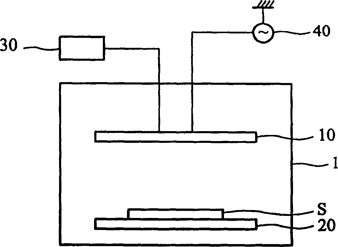
[0026] Figure 4 A schematic diagram showing a plasma processing apparatus according to a preferred embodiment of the present invention. The plasma processing device includes a processing chamber 1 , a gas supply system 30 and a power source 40 . Inside the processing chamber 1 , there is an upper electrode plate 60 and a lower electrode plate 20 . A substrate S to be subjected to plasma treatment can be placed on the lower electrode plate 20, such as a semiconductor substrate used in the semiconductor manufacturing process, or a glass substrate or transparent plastic substrate used in the TFT-LCD manufacturing process. The gas supply system 30 can supply gas into the processing chamber 1 . The power source 40 may be radio frequency (RF) for applying a voltage difference between the upper and lower electrode plates 60 and 20 to convert the gas in the processing chamber 1 into plasma.

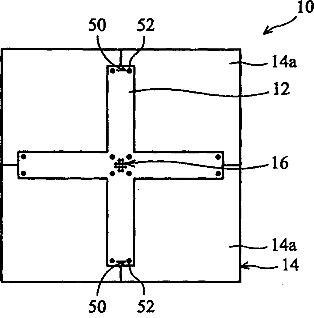
[0027] The present invention is characterized by the improvement of the upper electrode p...


PUM


Abstract

The invention provides a plasma processing unit, wherein the upper plate electrode comprises a gas demarcation strip and an insulating cover plate covered on the top of the gas demarcation strip, and plurality of mounting portions for mounting the gas demarcation strip and the insulating cover board, each mounting portion includes a screw and a nut. The invention can eliminate product defects and increase quality ratio.

Description

technical field [0001] The invention relates to a plasma processing device, in particular to a plasma processing device capable of avoiding arc discharge. Background technique [0002] In the TFF-LCD front-end array (array) manufacturing process, it is often necessary to use a plasma processing device for etching and deposition. For example, etching of an amorphous silicon layer or a polysilicon layer in a TFT is performed using a plasma processing apparatus. [0003] figure 1 A schematic diagram of a conventional plasma processing device is shown, which includes a processing chamber 1 with an upper electrode plate 10 and a lower electrode plate 20 inside the chamber 1 . A gas supply system 30 and a power source 40 are connected to the upper electrode plate 10, and the power source 40 may be radio frequency (radio frequency RF). The gas supply system 30 can supply gas into the cavity 1 , and the radio frequency is used to provide a voltage difference between the upper and...

Claims


Application Information

Patent Timeline
IPC IPC(8): C23F1/00G02F1/13H01J37/36H01L21/203H01L21/3065H01L21/363H01L21/465H05H1/46
Inventor 李孝忠黄庆德戴嘉宏陈虹瑞赖宏裕
Owner AU OPTRONICS CORP
Why Eureka
Try Eureka