Motor with built-in permanent magnets

A permanent magnet and motor technology, applied in the field of motors, can solve the problem that the difference in inductance cannot be made larger, and achieve the effect of improving anti-demagnetization and high output power

Inactive Publication Date: 2004-06-16
PANASONIC CORP
View PDF0 Cites 34 Cited by
  • Summary
  • Abstract
  • Description
  • Claims
  • Application Information

AI Technical Summary

Problems solved by technology

But the q-axis inductance of the prior art motor cannot be increased to such an

Method used


Image

  • Motor with built-in permanent magnets
  • Motor with built-in permanent magnets
  • Motor with built-in permanent magnets

Examples


Embodiment Construction

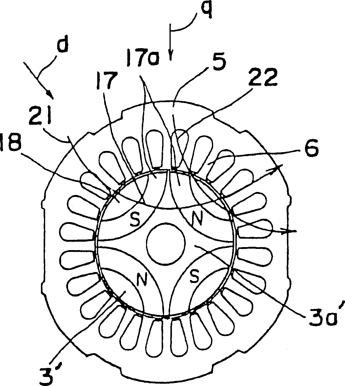
[0055] Referring now to the drawings, wherein the same or corresponding parts are denoted by the same reference numerals throughout the drawings, embodiments of the present invention will be described in detail with reference to the drawings. Figure 4 and 5 A motor with built-in permanent magnets of 4 poles is shown in the first embodiment. The motor includes a rotor 3 fixed on a rotating shaft 7 and a stator 2 on which the rotor 3 is installed.

[0056] The rotor 3 includes 4 sets of 2-layer permanent magnets 8a, 8b embedded in a rotor core 3a made of high magnetic permeability material. The 2-layer permanent magnet group is composed of an outer permanent magnet 8a and another inner permanent magnet 8b, and 4 sets of 2-layer permanent magnets 8a and 8b are arranged with alternating N and S poles on their outer peripheral sides. The inner and outer sides are defined in a radial direction with respect to the center of the rotor. Seen in a different way, the one-pole permane...


PUM


Abstract

A rotor of a motor includes a plurality of sets of permanent magnets 8a, 8b embedded in the rotor. Each includes a permanent magnet at an inner side and another permanent magnet at an outer side with a distance between them. Each permanent magnet 8a, 8b is formed like an arch projecting towards the center of the rotor. Magnetic flux flows easily through an interval between the permanent magnets at inner and outer sides, and the inductance in a q-axis is enlarged. Then, the reluctance torque is generated in addition to the magnet torque, and the motor has a high torque and a high output power.

Description

technical field [0001] This invention relates to electric motors incorporating permanent magnets in their rotors. Background technique [0002] Motors with a layer of permanent magnets in a rotor made of highly magnetically permeable material, such as iron, are known. As in prior art surface magnet motors, permanent magnets are added to the rotor surface. [0003] Recently, environmental problems have attracted sufficient attention. To save energy, motors with built-in permanent magnets, ie permanent magnets embedded in the rotor, are used instead of the mentioned surface magnet motors. [0004] figure 1 An example of a conventional built-in permanent magnet motor is shown. The motor consists of a rotor 3' and a stator 2. In this motor, each arc-shaped permanent magnet 17 extending relative to the center of the rotor 3' is embedded in a rotor core 3a' made of high magnetic permeability material or silicon steel sheet. shown in figure 1 The electric motor has 4 poles, ...

Claims


Application Information

Patent Timeline
IPC IPC(8): H02K1/27H02K21/14
CPCH02K1/276H02K21/14H02K1/2766
Inventor 本田幸夫村上浩楢崎和成伊藤浩神藤正行浅野能成角谷直之
Owner PANASONIC CORP
Why Eureka
Try Eureka