Interconnection structure of electric conductive wirings

A technology of conductive wiring and construction, applied in conductive connection, structural connection of printed circuit, connection of electrical components, etc., can solve problems such as adhesive flow obstruction

Active Publication Date: 2004-06-16
TOHOKU PIONEER CORP
View PDF2 Cites 18 Cited by
  • Summary
  • Abstract
  • Description
  • Claims
  • Application Information

AI Technical Summary

Problems solved by technology

In this way, the flow of the adhesive in the anisotropic conductive film 140 will be completely hindered at the end of the insulating layer 133, thereby making the short circuit problem of the above-mentioned wiring pattern more prominent.

Method used


Image

  • Interconnection structure of electric conductive wirings
  • Interconnection structure of electric conductive wirings
  • Interconnection structure of electric conductive wirings

Examples


Embodiment

[0057] Next, an example in which a pair of connection partners of the above-mentioned embodiment is connected to an organic EL display panel and a flexible printed circuit board will be described.

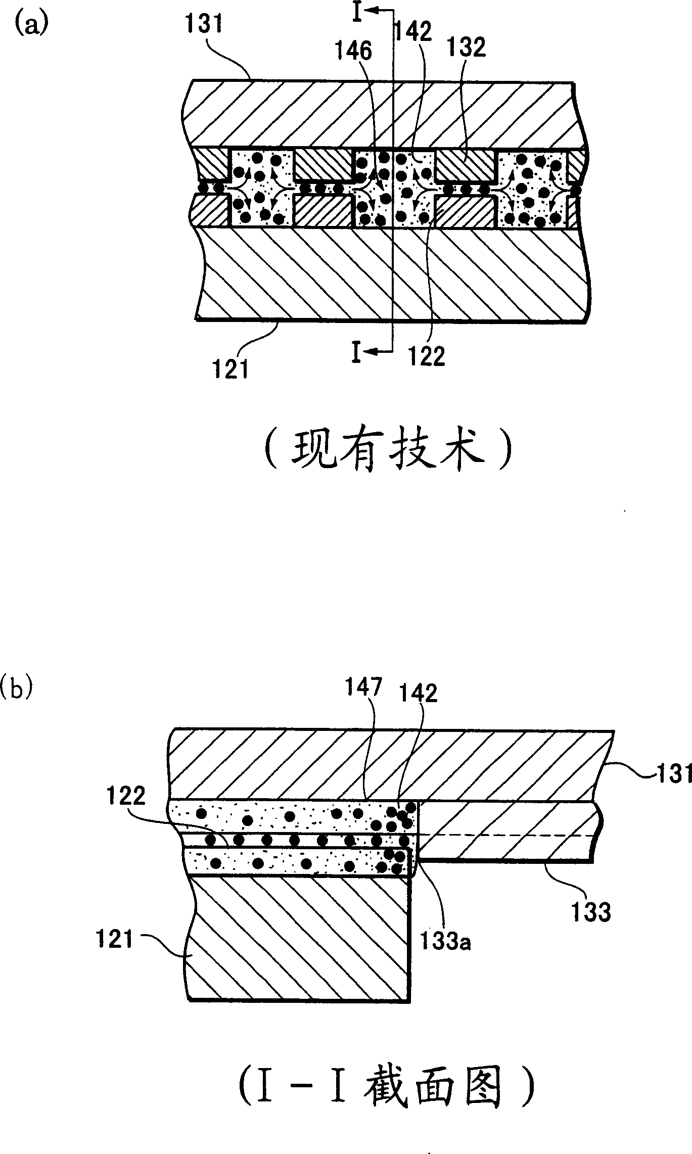
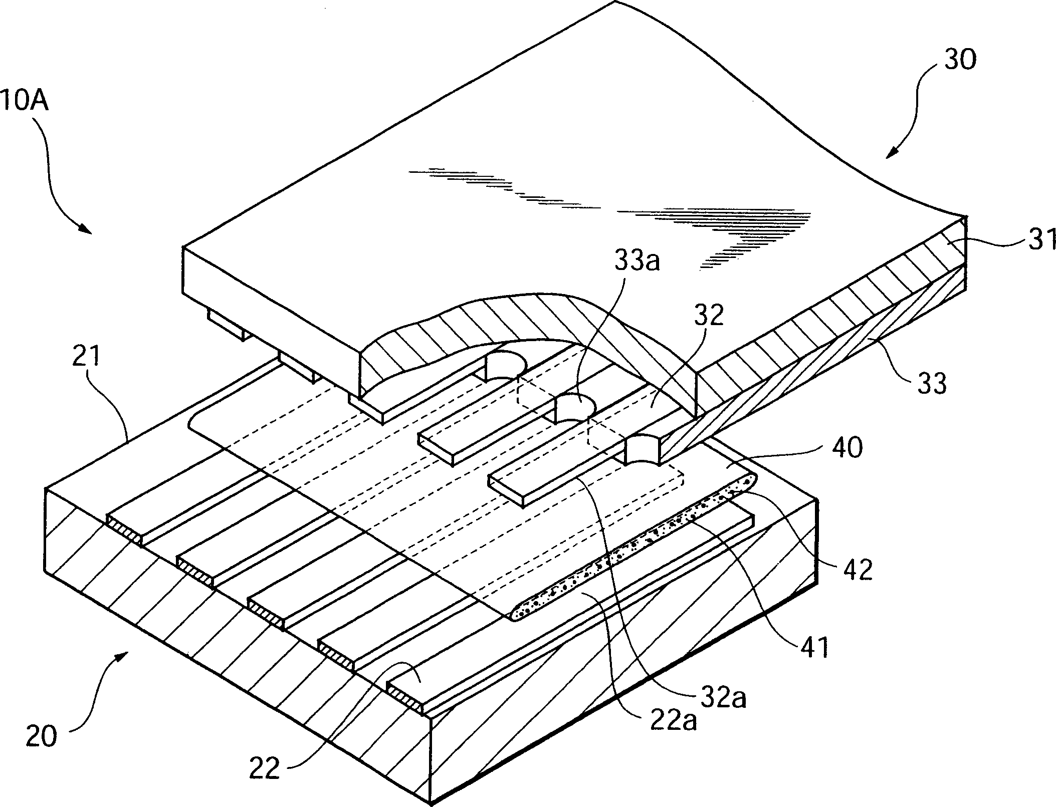
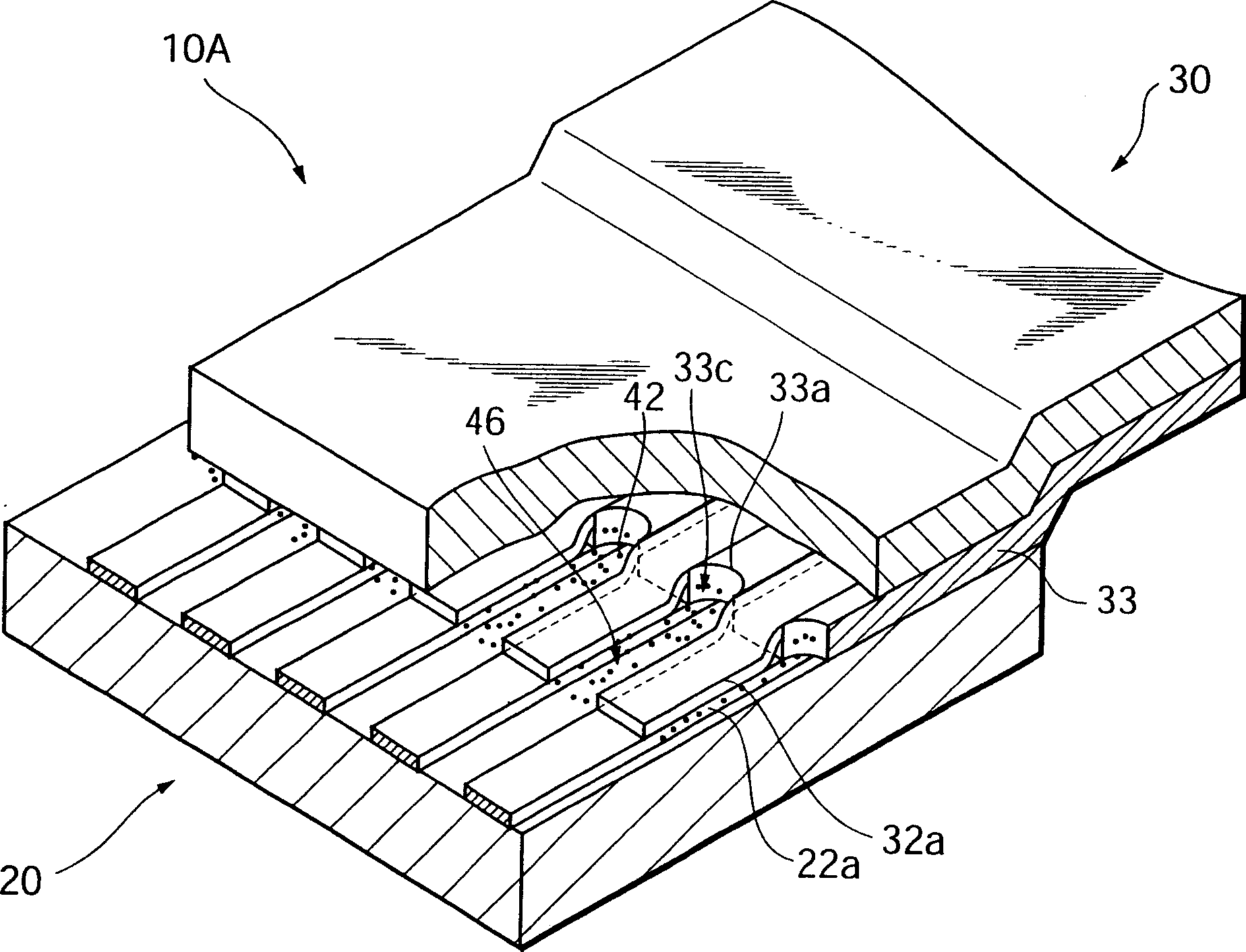
[0058] The organic EL display panel in this embodiment has a connection portion in which a wiring pattern of conductive wiring is formed on the surface of the substrate, and the connection object is thermocompression-bonded to the connection portion through an anisotropic conductive film. It is characterized in that recesses or cavities that allow conductive particles (moved by thermocompression) to stay are formed in gaps between wiring patterns on the surface of the substrate in the connecting portion.

[0059] According to the above-mentioned organic EL display panel, when other connection objects are connected to the above-mentioned connection part by thermocompression bonding, even the conductive particles of the anisotropic conductive film that move due to the pressure bonding...


PUM


Abstract

Provided is a connection structure of an electrically conductive wire, in which a wire pattern short circuit etc., accompanying movement of conductive particles to a wire pattern gap is avoided when conductive wires are connected by thermocompression bonding a couple of connected objects having wiring patterns of conductive wires formed on base surfaces through an anisotropic conductive film. A space 33c where conductive particles 42 stay is formed at a wiring pattern gap 46 of a conductive wire formed on the base surface. Conductive particles 42 moving to the wiring pattern gap 46 by thermocompression bonding are allowed to escape to the space 33c to prevent the conductive particles 42 from being too dense, thereby avoiding a wiring pattern short circuit.

Description

technical field [0001] The present invention relates to a connection structure of conductive wiring. Background technique [0002] As means for connecting conductive wiring between a pair of connection partners, the following technique is known. That is, an anisotropic conductive film (ACF; Anisotropic Conductive Film) is disposed in a connection portion between conductive wirings, and then thermocompression bonding is performed on the connection portion. Here, the anisotropic conductive film (ACF) is bonded with anisotropic conductivity by dispersing conductive particles (metal particles or metal-coated plastic particles, etc.) in a binder such as thermoplastic resin or thermosetting resin. agent film. Because individual electrical connections can be made to fine wiring patterns only through the thermocompression bonding process, this conductive film can be widely used to connect the panel electrode connection part of a flat display panel such as LCD or organic EL to a fl...

Claims


Application Information

Patent Timeline
Patent Type & Authority Applications(China)
IPC IPC(8): H05B33/06G09F9/00G09F9/30H01L27/32H01L51/50H01R11/01H05K1/14H05K3/32H05K3/36
CPCH01L27/3297H05K2201/09063H05K2201/09172H01L2924/0002H05K2201/09036H05K3/323H05K3/361H10K59/179H01L2924/00
Inventor 大峡秀隆
Owner TOHOKU PIONEER CORP
Why Eureka
Try Eureka