Driving apparatus for high acceleration revolution axis and application method thereof

A technology of acceleration and rotating shaft, applied in electromechanical devices, assembly machines, metal processing, etc., can solve problems such as mold or component damage

Inactive Publication Date: 2004-06-16
UI HLDG
View PDF0 Cites 0 Cited by
  • Summary
  • Abstract
  • Description
  • Claims
  • Application Information

AI Technical Summary

Problems solved by technology

[0003] In commonly used equipment, if the rotating shaft is moved too fast in the Z-axis direction, there is a possibility that the rotating shaft will contact the mold or parts at a faster speed, causing damage to the mold or parts

Method used


Image

  • Driving apparatus for high acceleration revolution axis and application method thereof
  • Driving apparatus for high acceleration revolution axis and application method thereof
  • Driving apparatus for high acceleration revolution axis and application method thereof

Examples


Embodiment Construction

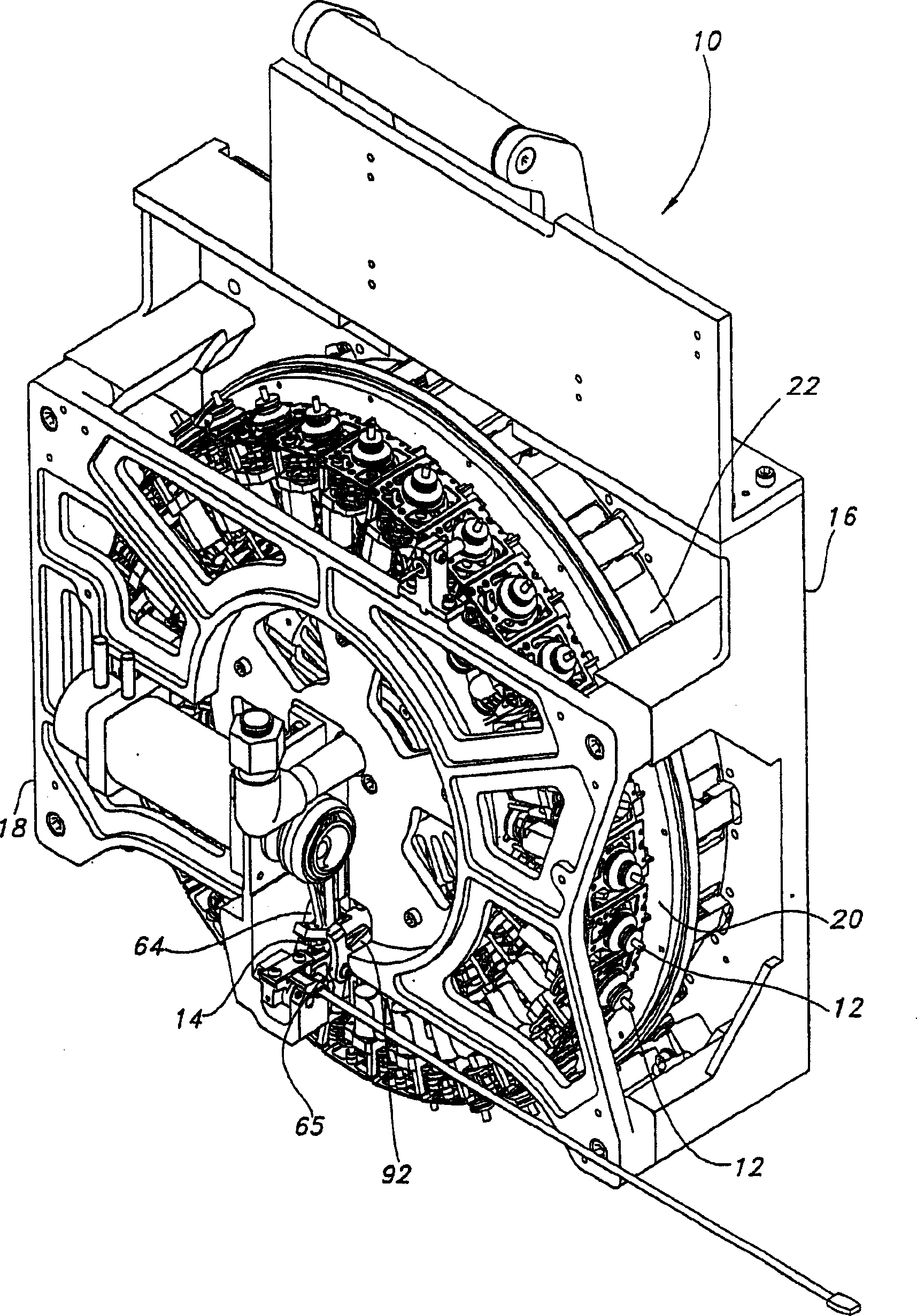
[0018] figure 1 Shown is a perspective view of a pick and place device 10 according to a preferred embodiment of the present invention. The pick and place device 10 can be used in pick and place equipment to pick up electronic components and place them at desired locations during assembly operations.

[0019] The pick and place device 10 includes a rear portion 16 of the pick and place device frame, and a front portion 18 of the pick and place device frame. A pivot support 20 is arranged between the front part 18 and the rear part 16 of the pick-and-place device support.

[0020] Spindle support 20 includes a plurality of pick and place heads 12 mounted thereon. A motor 22 is arranged in the device to drive the spindle support 20 relative to the pick and place device supports 16 , 18 .

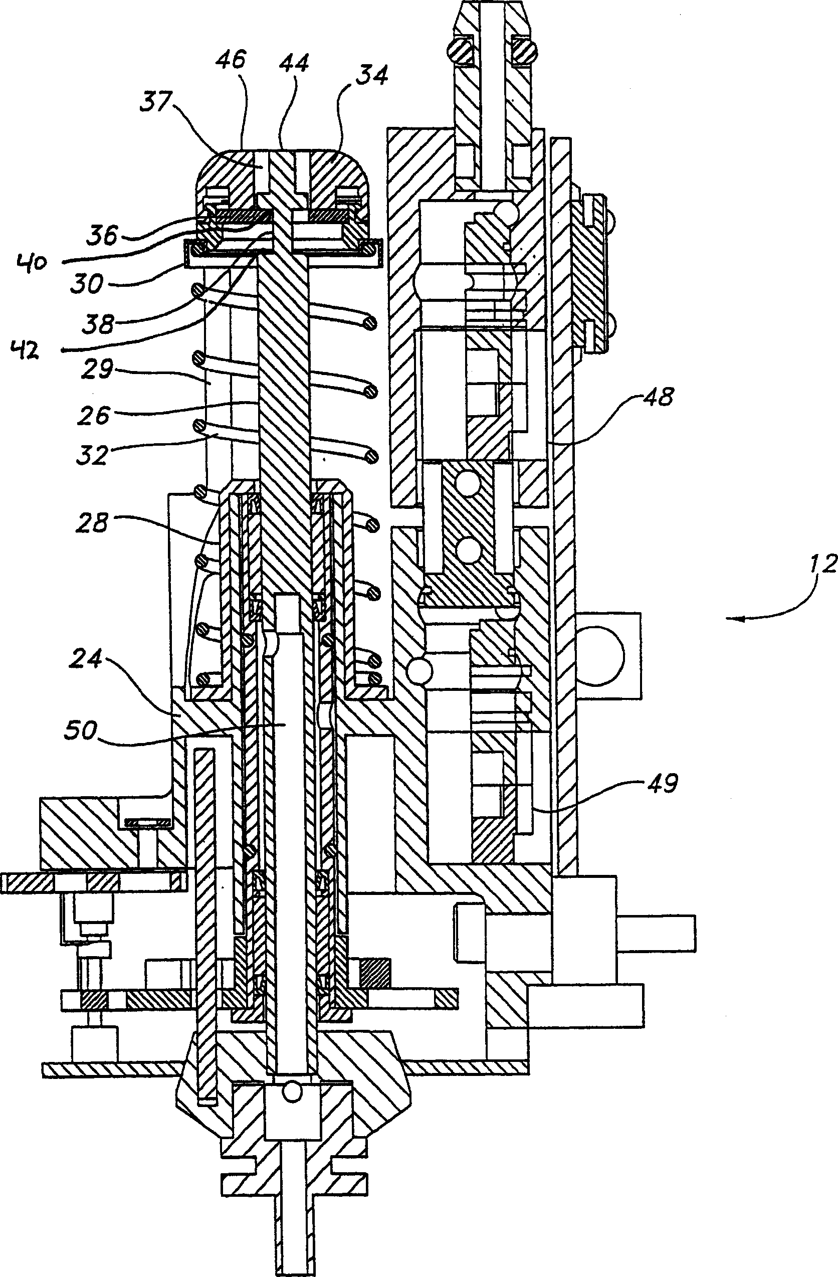
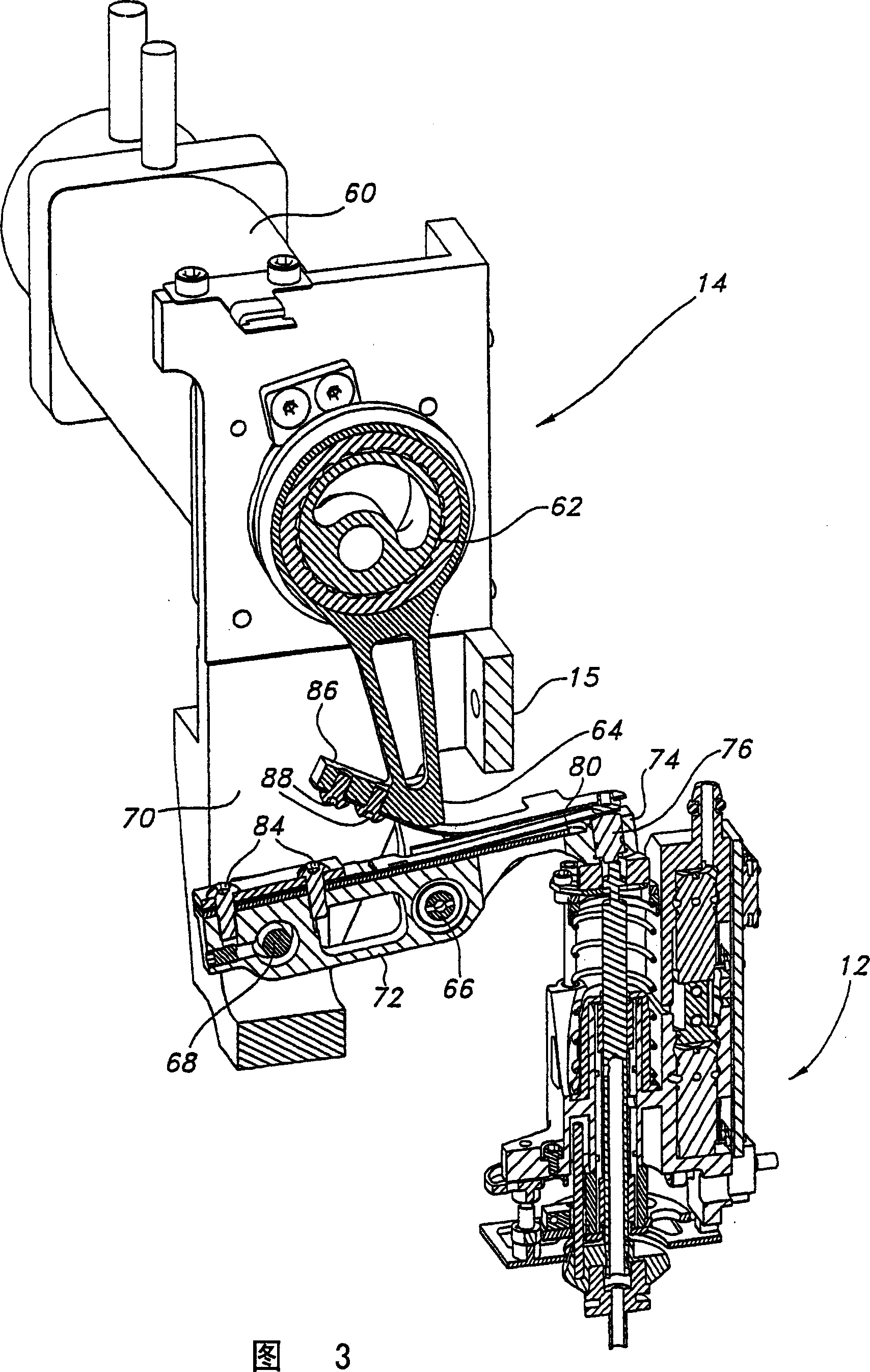
[0021] At the front part of the pick-and-place device 10 a spindle drive assembly 14 is arranged. 3-5 show detailed views of the spindle drive assembly 14 .

[0022] Figure 2-5 A pick a...


PUM


Abstract

An apparatus for moving a spindle along a longitudinal axis, the apparatus includes a spindle; a drive member for moving said spindle over a range of travel along said longitudinal axis in a first direction; a spring for applying a first force in combination with a second force to the spindle in the first direction; a stop element arranged so as to disengage the second force, such that when said spindle is within a first portion of said range of travel, said first force is applied to said spindle in combination with said second force, and when said spindle is within a second portion of said range of travel, said stop element disengages said second force so only said first force is applied to said spindle.

Description

technical field [0001] The present invention relates to a pick and place device and method of using the same, and more particularly, the present invention relates to a method of driving a shaft at a high speed with high precision. Background technique [0002] The present invention generally relates to, but is not limited to, machinery known in the electronics assembly industry such as pick and place equipment. In pick-and-place equipment, a rotating shaft mounted on the pick-and-place head comes into contact with molds or other electronic components to pick them up. The spindle assembly is then moved to another location and the molds or parts picked up by the spindle are placed in place for assembly. In order to minimize assembly time, it is practical to move the shaft assembly at a high speed in the Z-axis or vertical axis. [0003] In commonly used equipment, if the rotating shaft is moved too fast in the Z-axis direction, there is a possibility that the rotating shaft ...

Claims


Application Information

Patent Timeline
Patent Type & Authority Applications(China)
IPC IPC(8): B23P19/00B23Q5/00H01L23/48H02K7/075H05K13/04
CPCY10T74/1418H02K7/075Y10T74/1447B23Q5/00
Inventor K·A·吉斯克斯S·W·亚尼西维茨D·J·希巴德D·M·维斯J·E·达内克J·W·特里普
Owner UI HLDG
Why Eureka
Try Eureka