Fluid sprayer and spraying method

An injector and fluid technology, applied in the direction of combustion methods, gas fuel burners, burners, etc., can solve problems such as interruption of work, reduction of output, increase of cost, etc., to reduce thermal stress, increase versatility, and reduce possibility and the effect of running costs

Inactive Publication Date: 2004-06-23
UNITED TECH CORP
View PDF1 Cites 23 Cited by
  • Summary
  • Abstract
  • Description
  • Claims
  • Application Information

AI Technical Summary

Problems solved by technology

Therefore, changing the type of fuel burned in the system requires maintenance of the injectors, thereby interrupting work, reducing production and increasing costs

Method used


Image

  • Fluid sprayer and spraying method
  • Fluid sprayer and spraying method
  • Fluid sprayer and spraying method

Examples


Embodiment Construction

[0021] The invention will now be described in more detail hereinafter with reference to the accompanying drawings showing preferred embodiments of the invention. However, the invention may be embodied in many different forms and should not be construed as limited to the embodiments set forth herein; rather, these embodiments are provided so that this disclosure will be thorough and complete, and will fully convey to those skilled in the art scope of the invention. Like reference numerals refer to like elements throughout.

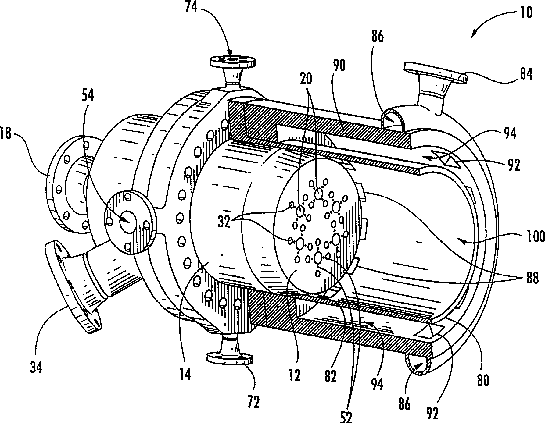
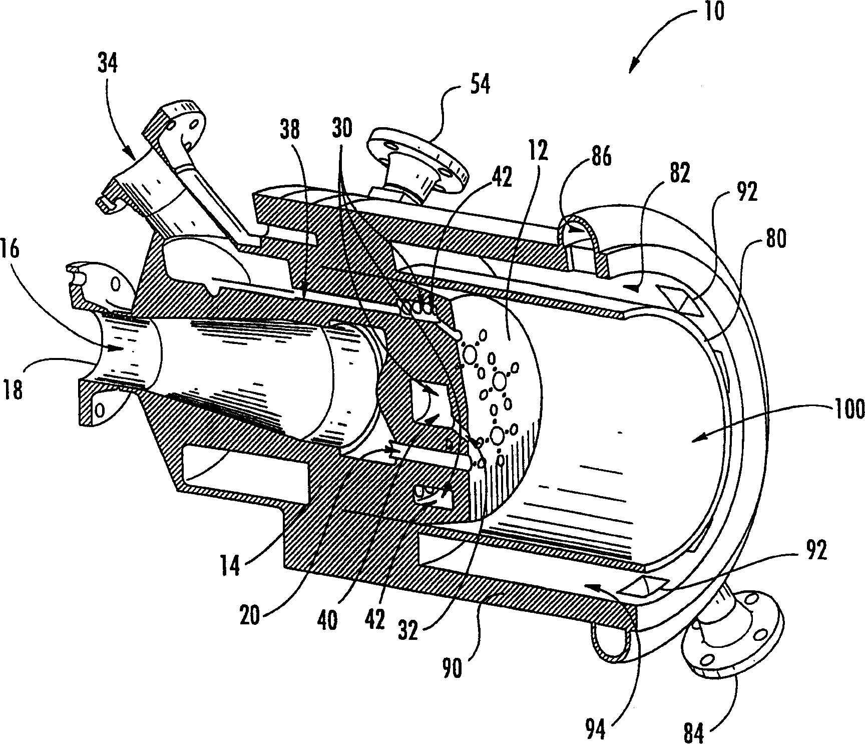
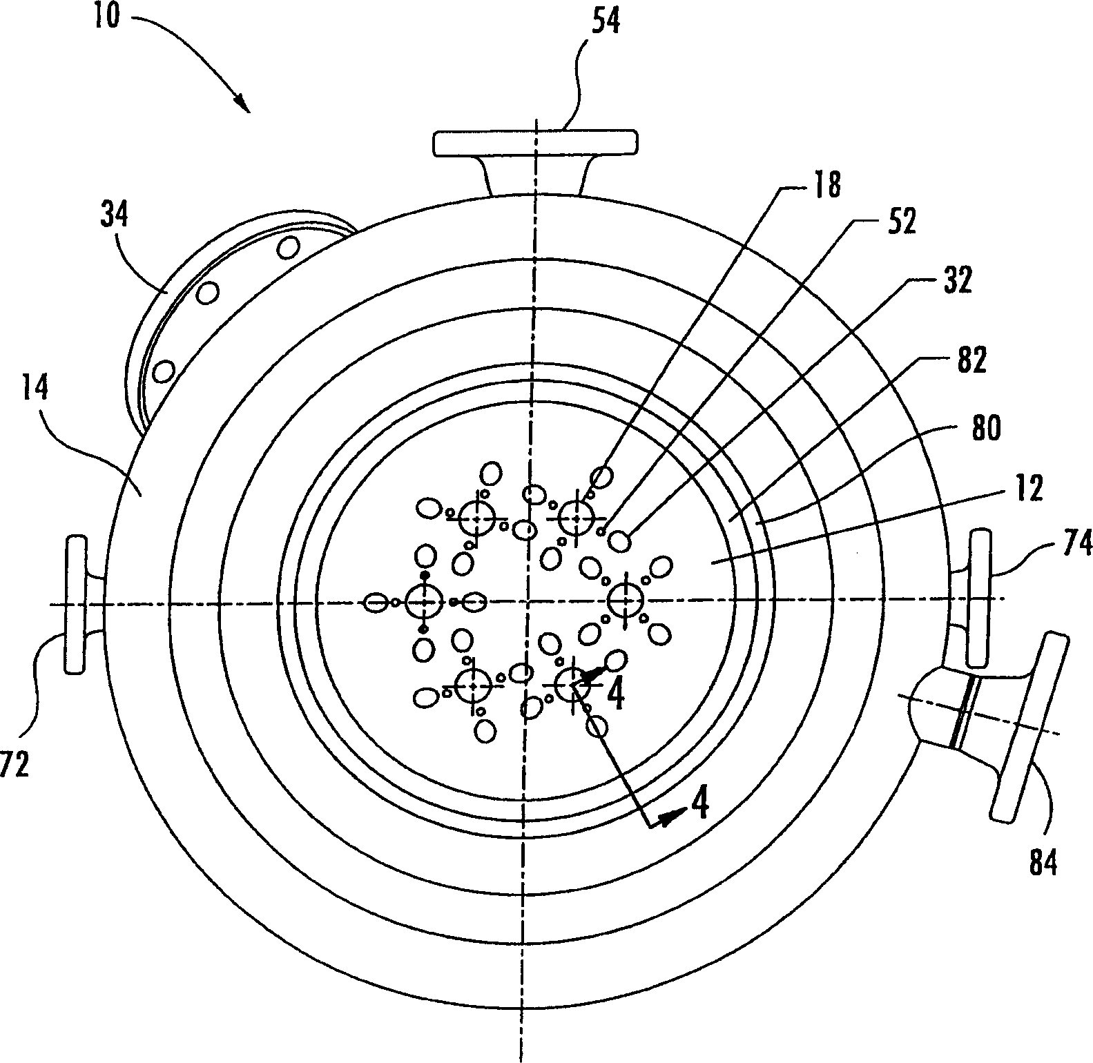
[0022] figure 1 Shown is an injector 10 for injecting fluid into a combustion chamber 100 in accordance with the present invention. The injector 10 has an injector body 14 facing the injector front 12 of the combustion chamber 100 . The injector body 14 also includes a plurality of orifices 20, 32, 52 in fluid communication with one or more inlets 18, 34, 54 as will be described further below. Fluid enters the injector body 14 through inlets 18 , 34 , 5...


PUM


Abstract

There are provided an injector and an associated method for injecting and mixing gases, comprising a carbonaceous fuel and oxygen, in a combustion chamber of a combustion device. The injector has jets, which can be used to separately inject different combustion fuels. The injector is compatible with combustion devices that inject only gases, for example, a reheater that provides initial combustion in a power generation cycle or a reheater that recombusts a discharged gas from a gas generator and turbine. Further, the injector defines an annular space through which a recycle gas can be injected into the combustion chamber to lower the combustion temperature.

Description

technical field [0001] The present invention relates generally to apparatus and methods for injecting fluids, and more particularly, to an injector and associated method for injecting combustible fluids into a combustion chamber. Background technique [0002] Combustion of carbon-based compounds, or carbon-containing fuels, is widely used to generate power and electricity. In a typical power generation system, a carbonaceous fuel such as natural gas is mixed with an oxidant and burned in a combustion device called a gas generator. The resulting combusted gases are exhausted into a turbine that is mechanically coupled to a generator, causing the turbine to spin. The combusted gases are then discharged into one or more additional combustion devices called regenerators, where they are mixed with additional fuel and / or oxidant for subsequent combustion. The regenerator, which develops a pressure typically lower than that produced by the gas generator, discharges the regenerate...

Claims


Application Information

Patent Timeline
Patent Type & Authority Applications(China)
IPC IPC(8): F23R3/28F02C3/20F02C3/34F02C7/18F02C7/22F23D11/38F23D14/58F23D17/00F23K5/00F23K5/22
CPCF23K5/002F23D17/002F23D14/58F23N2035/28F23D11/38F23K5/22F23N2235/28
Inventor 肯尼思·M·斯普劳斯戴维·R·马修斯罗伯特·J·詹森
Owner UNITED TECH CORP
Why Eureka
Try Eureka