Plasma processing method

A processing method and plasma technology, applied in the field of perforation operation, can solve problems such as poor ignition of the arc, ignition failure, weak guiding arc force, etc., and achieve the effects of avoiding nozzle damage, suppressing deterioration, and prolonging life

Inactive Publication Date: 2004-06-30
KOMATSU SANKI
View PDF1 Cites 11 Cited by
  • Summary
  • Abstract
  • Description
  • Claims
  • Application Information

AI Technical Summary

Problems solved by technology

Due to (A) (B), the nozzle will be excessively melted by the guided arc
In addition, setting the initial height to a relatively high height in this way will lead to the problem of poor ignition of the arc.
That is, according to the case of (A), although it is necessary to set a larger pilot current, when the current is low due to insufficient adjustment of the pilot current, the force of the pilot arc is weak and cannot be transformed into the main arc, thus make the ignition fail
Here, although in order to reduce the effort of adjusting the pilot current, it can be considered to fix the pilot current at the highest value that the machine can output, but this situation will lead to faster nozzle melting caused by the pilot arc.
[0010] In addition, in the technique of the prior invention described above, by rapidly converting the pilot arc to the main arc, it can be expected that the effect of suppressing nozzle deterioration to a certain extent can be expected, but since the initial height is set to a relatively high position (cutting height about 2 times that of ), so it can be said that there is still room for improvement

Method used


Image

  • Plasma processing method
  • Plasma processing method
  • Plasma processing method

Examples


Embodiment Construction

[0024] Next, specific embodiments of the plasma processing method in the present invention will be described one by one with reference to the accompanying drawings.

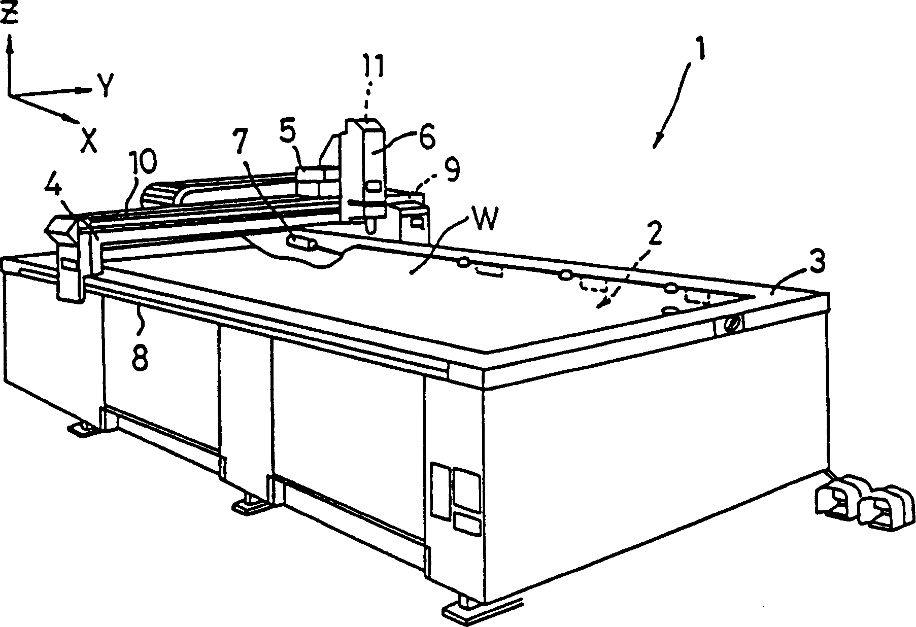
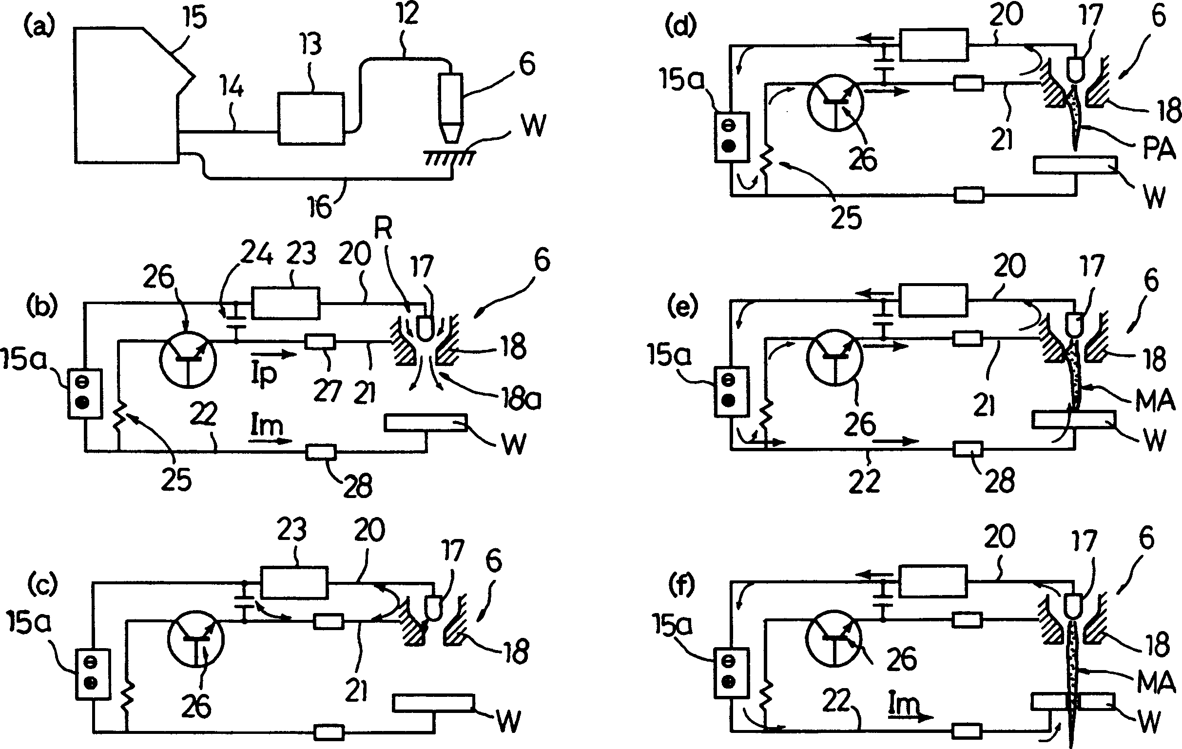
[0025] figure 1 It is an overall perspective view showing a plasma cutting apparatus according to an embodiment of the present invention. in addition, figure 2 (a) is a schematic configuration diagram showing main parts of the plasma cutting apparatus in this embodiment, and (b) to (f) of the same figure are explanatory diagrams showing a plasma arc generating circuit and its operation.

[0026] In the plasma cutting device 1 of the present embodiment, as figure 1As shown, a cutting table (cutting platform) 2 supporting a steel plate W as a material to be cut (processed workpiece) is arranged in the inner space of a rectangular frame 3, and at the same time, a door-shaped movement across the frame 3 is provided. A beam 4 on which a carriage 5 is fitted, on which a plasma cutting torch 6 is mounted.

[0027...


PUM


Abstract

The plasma torch is positioned at an initial level which is the distance between the plasma torch and a steel plate when generating a plasma arc to start piercing operation and which has been set equal to a cutting level which is the distance between the plasma torch and the steel plate when carrying out cutting operation. After generation of the plasma arc, the plasma torch is immediately raised to a piercing level which is more distant from the steel plate W than the initial level and piercing operation is performed at the piercing level. After completion of the piercing operation, the plasma torch is lowered to the cutting level to start cutting operation. Just after transfer from a pilot arc into a main arc, a pilot current is cut off by turning a transistor off. Not only damage to a nozzle caused by spatter generated during piercing is prevented but also the deterioration of the nozzle owing to a pilot arc is restrained, whereby the service life of the nozzle is significantly increased.

Description

technical field [0001] The present invention relates to a plasma processing method for piercing and cutting using a plasma arc generated from a plasma cutting torch, and more particularly, to a plasma processing method including a piercing operation which can improve the life of a nozzle of a plasma cutting torch. Background technique [0002] The plasma processing method using the high-density heat of the arc with the plasma column that shrinks mechanically and electrically is widely used in actual processing because it can achieve high-precision and high-efficiency cutting. In this plasma processing method, generally, a plasma arc is generated from a plasma torch, the plasma arc is stably continued, and the plasma torch is moved to perform cutting processing. [0003] The above-mentioned plasma cutting torch has an electrode and a nozzle provided to cover the electrode, and the plasma gas is ejected to the material to be cut through a passage defined between the electrode ...

Claims


Application Information

Patent Timeline
Patent Type & Authority Applications(China)
IPC IPC(8): B23K10/00
CPCB23K10/006B23K10/00
Inventor 山口义博加端哲也入山孝宏
Owner KOMATSU SANKI
Why Eureka
Try Eureka