Method for calibrating structure optical vision sensor

A visual sensor and calibration method technology, applied in the field of measurement, can solve the problems of a small number of calibration points, low image point extraction accuracy, easy reflection of teeth, etc., and achieve the effect of high accuracy

Inactive Publication Date: 2004-06-30
BEIHANG UNIV
View PDF0 Cites 49 Cited by
  • Summary
  • Abstract
  • Description
  • Claims
  • Application Information

AI Technical Summary

Problems solved by technology

This method has the following problems: First, because the tooth edges are easy to reflect light, the extraction accuracy of the image point is low
Second, due to the light intensity distribution of the bright spot itself, it is d

Method used


Image

  • Method for calibrating structure optical vision sensor
  • Method for calibrating structure optical vision sensor
  • Method for calibrating structure optical vision sensor

Examples


Embodiment

[0056] The actual design of the structured light vision sensor is as follows: Image 6 shown. 10 is the housing of the sensor, 11 is the window for the CCD to observe the scene, and 12 is the exit port of the laser. The positions of CCD and laser in the sensor are different, and their parameters are also different.

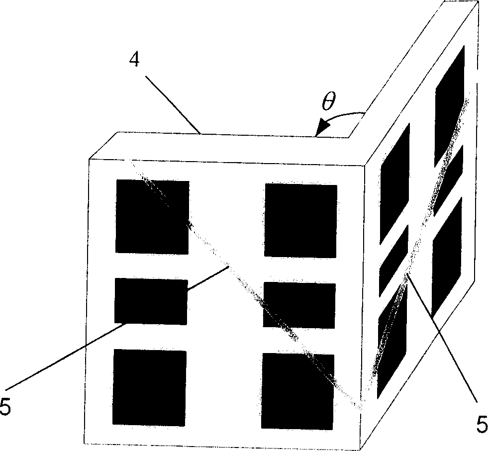
[0057] Following the steps described above, use the image 3 The targets shown (θ = 90°) were calibrated for three specific sensors.

[0058] Sensor one:

[0059] ·Camera perspective projection imaging model parameters

[0060] R = 0.135832 0.171788 0.975725 0.843045 - 0.537361 - 0.022753 0.520408 ...


PUM


Abstract

The invention refers to the improvement of sensor scaling method in structured light three dimension vision measurement. The steps are: sets target mark, fixes sensor, collects image, gets target mark coordinate, irradiates structured light, gets the coordinate of light, gets the coordinate at any spot of the structured light strap. Calculates the three dimension object coordinate, calculate R and t, and calculates a, b, c, d.

Description

technical field [0001] The invention belongs to the technical field of measurement and relates to the improvement of a sensor calibration method in structured light three-dimensional vision detection. Background technique [0002] Among many visual inspection methods, structured light three-dimensional visual inspection is widely used in the measurement of workpiece integrity and surface flatness; automatic inspection of microelectronic devices (IC chips, PC boards, BGA), etc.; soft, fragile Detection of parts; detection of three-dimensional shapes of various molds; visual guidance of robots, etc. Structured light visual inspection technology has been more and more widely used in industrial environments due to its characteristics of large range, large field of view, fast measurement speed, easy extraction of light strip images and high precision. The effective calibration method of structured light vision sensor model parameters has always been an important research content...

Claims


Application Information

Patent Timeline
IPC IPC(8): G01B11/24G01B11/30G06T7/00
Inventor 张广军魏振忠徐园
Owner BEIHANG UNIV
Why Eureka
Try Eureka