Heat-pump water heater

A hot water supply, heat pump technology, applied in residential hot water supply systems, heat pumps, heating methods, etc., can solve problems such as difficulty in coping with a wide range of hot water supply loads, reducing efficiency, and increasing the temperature of hot water supply.

Inactive Publication Date: 2004-06-30
PANASONIC CORP
View PDF1 Cites 28 Cited by
  • Summary
  • Abstract
  • Description
  • Claims
  • Application Information

AI Technical Summary

Problems solved by technology

[0011] As mentioned above, in the conventional heat pump hot water supply device, since the heating control is performed regardless of the hot water supply load, it is difficult to cope with a wide range of hot water supply loads.
In addition, it is difficult to combine reactivity and stability of hot water temperature control
Moreover, sometimes the increase in hot water supply temperature is worsened, and there are problems such as lowering efficiency.

Method used


Image

  • Heat-pump water heater
  • Heat-pump water heater
  • Heat-pump water heater

Examples


no. 1 Embodiment

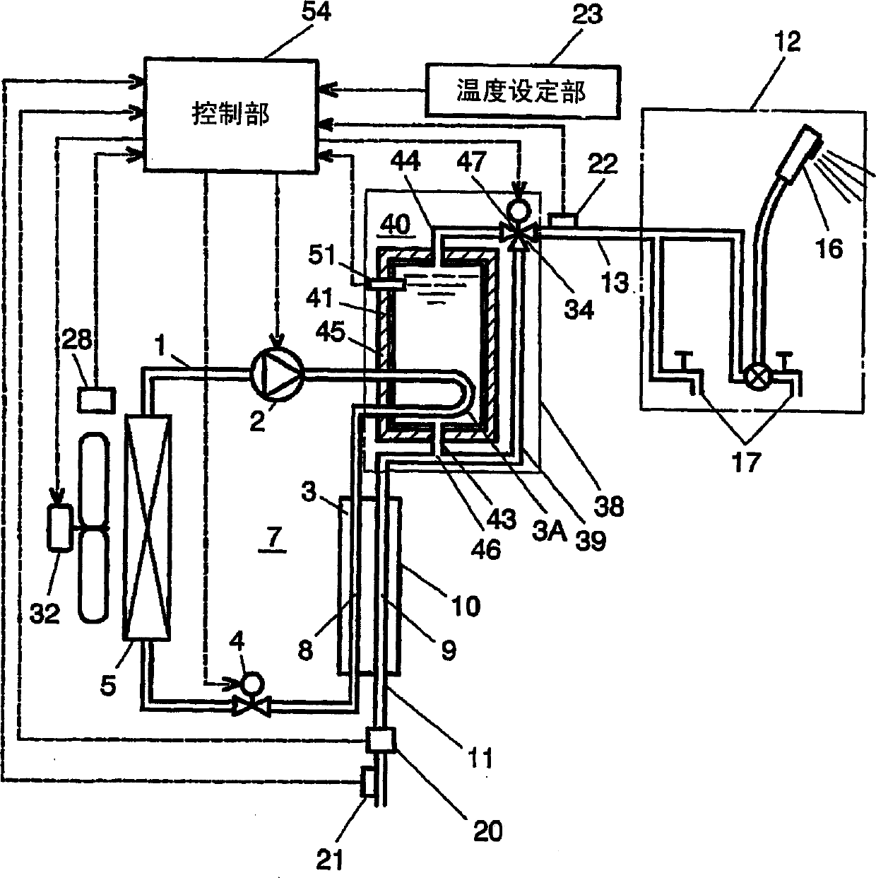
[0031] Fig. 1 is a block diagram of a heat pump hot water supply device according to a first embodiment of the present invention. In FIG. 1 , in the heat pump cycle mechanism 7 , the compressor 2 , the first radiator 3A, the second radiator 3 , the decompression unit 4 and the heat absorber 5 are connected to form a closed circuit through the refrigerant flow path 1 . . The heat pump cycle mechanism 7 is a supercritical heat pump cycle mechanism that uses, for example, carbon dioxide gas as a refrigerant, and the refrigerant pressure on the high-pressure side is equal to or higher than the critical pressure of the refrigerant. The compressor 2 is driven by a built-in electric motor (not shown), and compresses the drawn refrigerant to a critical pressure and discharges it. In addition, the heat exchanger 10 has a water flow path 9 that exchanges heat with the refrigerant flow path 8 of the second heat radiator 3 . The water supply pipe 11 that directly supplies tap water to t...

no. 2 Embodiment

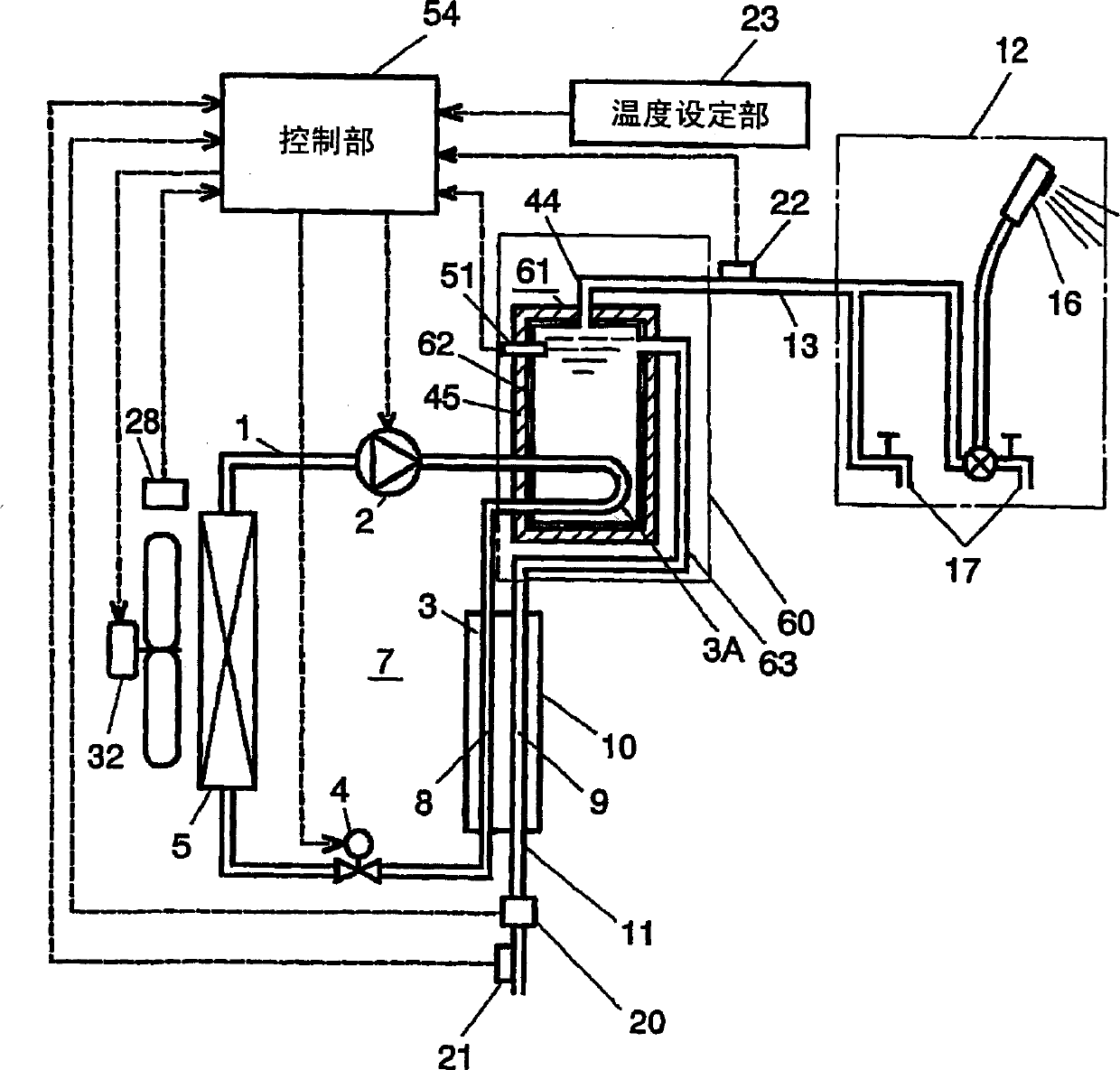
[0049] Fig. 2 is a block diagram of a heat pump hot water supply device according to a second embodiment of the present invention. In FIG. 2 , the difference from the configuration of the first embodiment is that a heating unit 60 is provided instead of the heating unit 38 . The heating unit 60 is provided with a heat storage unit 61 aligned with the hot water supply circuit 13 . Another difference is that in the heat storage part 61 , the inlet pipe 63 is arranged on the upper part of the storage tank 62 and the hot water in the storage tank 62 and the water (hot water) from the heat exchanger are mixed inside the storage tank 62 . And the storage temperature when the storage tank 62 performs a heat-retaining operation is set to the same temperature as the target temperature (for example, 45 degreeC) of hot water supply. However, if the storage temperature is low, the storage tank 62 has a large capacity.

[0050] In the above structure, if the heat exchanger 10 starts to s...

no. 3 Embodiment

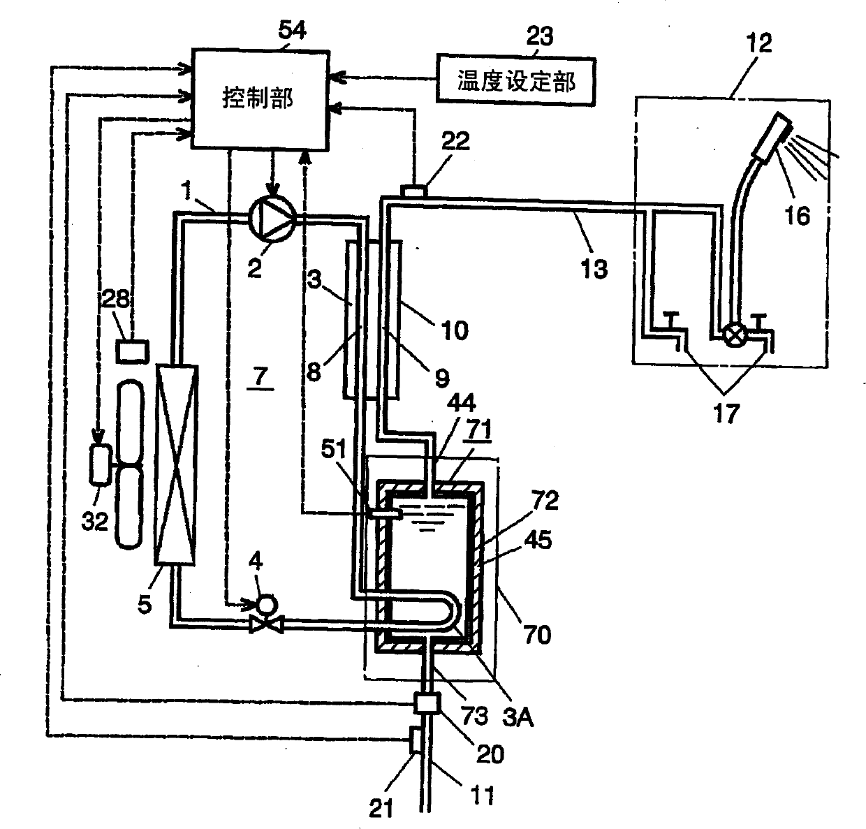
[0053]Fig. 3 is a block diagram of a heat pump hot water supply device according to a third embodiment of the present invention. In FIG. 3 , the difference from the configuration of the second embodiment is that a heating unit 70 is provided instead of the heating unit 60 . The heating unit 70 is provided with a heat storage unit 71 aligned with the water supply pipe 11 . Another difference is that an inlet pipe 73 is arranged at the bottom of the storage tank 72 of the heat storage unit 71 . And the storage temperature when the storage tank 72 performs a heat-retaining operation is set to the same temperature as the target temperature (for example, 45 degreeC) of hot water supply.

[0054] In the above structure, if the hot water is supplied from the completely cooled state of the heat exchanger 10 , the cold water will flow into the bottom of the storage tank 72 from the water supply pipe 11 , and the warm water in the storage tank 72 will flow out from the outlet pipe 44 ....


PUM


Abstract

A flash water heater using a heat pump includes a heat exchanger in which a refrigerant flow path exchanges heat with a water flow path. Tap water is led directly to the water flow path, and hot water supplied from the water flow path is used. The water heater includes at least one of the following elements: 1) a load setter for setting a heating amount in the heat exchanger, and a heating controller for regulating a heating amount in response to an amount set by the load setter; 2) a heater for heating water flowing through the water flow path in the heat exchanger and water flowing the path before and after the heat exchanger; 3) plural compressors; and 4) plural heat-pump cycles. The water heater is excellent in start-up of hot water temperature when the hot water supply starts, controllability, and efficiency.

Description

technical field [0001] The invention relates to an instant boiling water type heat pump hot water supply device. Background technique [0002] Hitherto, a hot water supplier utilizing burning gas or oil has been used as an instant boiling water type hot water supply device. These instantaneous boiling water type hot water supply devices have the characteristics of rapid temperature rise and strong performance, but on the other hand, there are also unavoidable air pollution due to exhaust gas, insecurity about direct combustion, and combustion noise. The problem. On the other hand, a heat pump type hot water supplier that stores hot water in a large hot water storage tank and supplies hot water solves the problem of a hot water supplier that operates by combustion, and has better thermal efficiency due to the heat pump. However, the above-mentioned hot water supplier has problems in construction such as a large hot water storage tank, weight, and installation space. Althou...

Claims


Application Information

Patent Timeline
Patent Type & Authority Applications(China)
IPC IPC(8): F24D17/02F24D19/10F25B9/00F25B30/02
CPCF25B2700/2106F24D17/02F24D19/1054Y02B30/743F25B9/008F25B2400/06F25B2309/061F25B2400/075F25B2700/21161F25B2600/025Y02B30/741Y02B30/12F25B30/02F25B2600/2513F25B2600/02F25B2600/112F25B2600/021Y02B30/70F24H15/215F24H15/238F24H15/281F24H15/414F24H15/385F24H15/258F24H15/175F24H15/38F24H15/223F24H15/219
Inventor 国本启次郎渡边竹司近藤龙太松本聪今林敏
Owner PANASONIC CORP
Why Eureka
Try Eureka