Downward type back light module

A backlight module, direct-type technology, applied in optics, nonlinear optics, mirrors, etc., can solve problems such as unreduced thickness, yellowing of the screen, and short service life of printing ink

Inactive Publication Date: 2004-07-14
AU OPTRONICS CORP
View PDF0 Cites 16 Cited by
  • Summary
  • Abstract
  • Description
  • Claims
  • Application Information

AI Technical Summary

Problems solved by technology

In the prior art, a layer of special printing ink (such as image 3 As shown), to break up the energy of light, although this method can solve the problems of poor uniformity and easy to see the main body of the light source, but for the need to keep a certain distance between the diffuser plate and the lamp tube, The disadvantages of increased thickness due to the absorption of light energy by the printing ink itself, and the decrease of screen brightness, as well as the problem

Method used


Image

  • Downward type back light module
  • Downward type back light module
  • Downward type back light module

Examples


no. 1 example

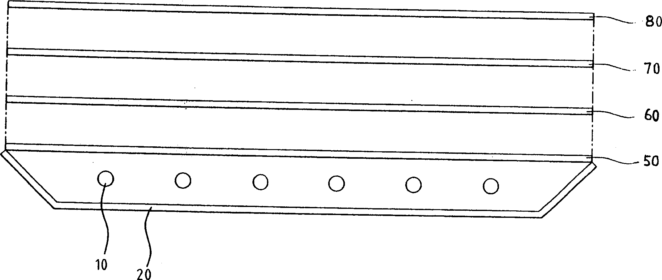
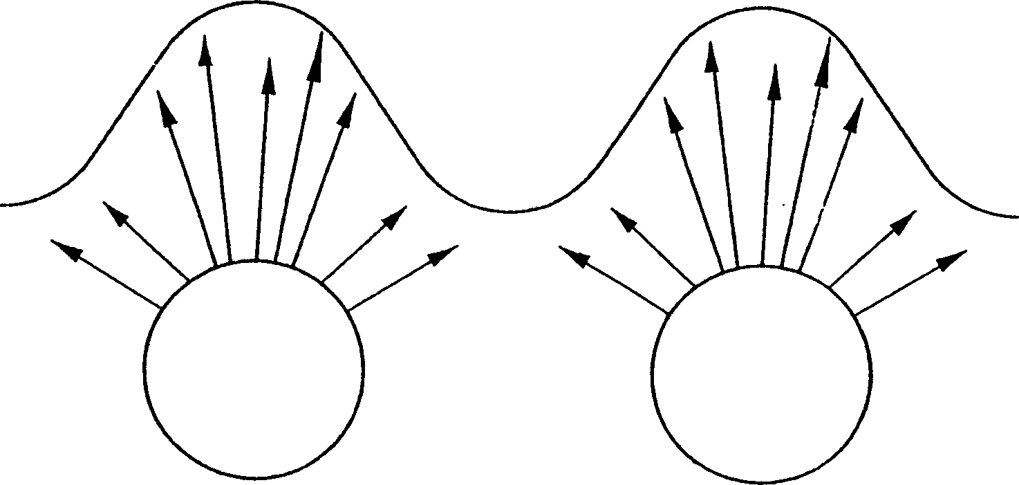
[0029] Such as Figure 4 As shown, the light source 240 is placed above the reflecting plate 250. The light source 240 is a lamp tube 240 with a diameter Φ of about 2.6 millimeters (mm) and is located in the slightly arc-shaped reflecting groove of the reflecting plate 250. It can be seen from the figure that the reflective groove surrounds the light source 240 half-circumferentially, and the central part of the reflective groove has a first reflective surface 210 that protrudes upward in an arc shape, and its radius of curvature is about 1 / 2 of the diameter of the light source 240. 2 to 3 times; the edge portion of the left side of the reflective groove has a second reflective surface 220, the inclination angle is about 20 degrees to 40 degrees, preferably 30 degrees; and the third reflective surface 230, its The inclination angle is about 40°-70°, preferably 60°, and the right side also has the same symmetrical structure. in addition, Figure 4 h in 1 Represents the dista...

no. 2 example

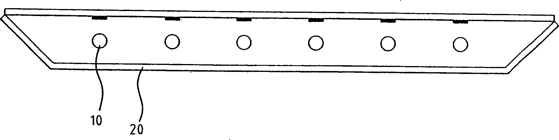
[0034] see Figure 7 , the initial structure and correlation coefficient are as follows Figure 4 with Figure 5 As shown, but in Embodiment 2, a non-printed light guide plate 260 is installed on the light source 240 to replace the existing diffuser plate. The radius of curvature of the light guide plate 260 is R 2 , where R 2 R 1 , in this embodiment, the material of the non-printed light guide plate 260 is a transparent acrylic material, which has a slightly arc-shaped light-transmitting groove on the side facing the light source 240, which is used to radiate light toward the light source 240. The position of the light transmission groove corresponds to the reflection groove of the reflection plate 250 , and the combination of the two can cover the light source 240 therein. In addition, the light guide plate 260 has a plurality of protrusions 270 at the connecting portion between the light-transmitting groove and the light-transmitting groove to reflect part of the refr...


PUM


Abstract

The downward back light module includes several light sources to emit light; arced reflecting concave mirrors, each of which has one raised first reflecting surface in the center, right and left symmetrical structures of one second reflecting surface and one third reflecting surface, in the same amount said the light sources hemi-surrounding each light source separately; one non-printed light guiding plate to guide light upwards and with several arced scattering transparent notches in the side opposite to the light sources; and one covering hood to cover and support the reflecting concave mirrors and the light guiding plate while leaving the transparent side of the light guiding plate un-covered.

Description

technical field [0001] The invention relates to a direct-down backlight module for a liquid crystal display device, in particular to a direct-down backlight module with a plurality of light sources and a plurality of reflective curved surfaces corresponding to the number of light sources in a reflector. Background technique [0002] In recent years, with the continuous improvement of the accumulation of components in various parts of the computer, the requirements for peripheral products are also constantly moving towards light, thin, short, small, and low power requirements. Compared with other display devices, such as CRT, LCD is a device with small size and low power consumption. Since the liquid crystal molecule itself is not a spontaneous light-emitting device, the LCD needs a light source in addition to the liquid crystal screen. [0003] At present, the light sources commonly used in LCD screens are cold cathode tubes (Cold Cathode Fluorescent Lamp-CCFL) and hot cath...

Claims


Application Information

Patent Timeline
IPC IPC(8): G02B5/10G02F1/13357
Inventor 何益君
Owner AU OPTRONICS CORP
Why Eureka
Try Eureka