Optical disk device

An optical disc device, optical disc technology, applied in the directions of beam source, optical recording head, optical recording system, etc., can solve problems such as inapplicability

Inactive Publication Date: 2004-07-28
TEAC CORP
View PDF1 Cites 3 Cited by
  • Summary
  • Abstract
  • Description
  • Claims
  • Application Information

AI Technical Summary

Problems solved by technology

In addition, the trial-written data in the data area must be rewritten, so it is limited to CD-RW discs, etc., and there is a problem that it cannot be applied to discs that cannot be rewritten.

Method used


Image

  • Optical disk device
  • Optical disk device
  • Optical disk device

Examples


Embodiment Construction

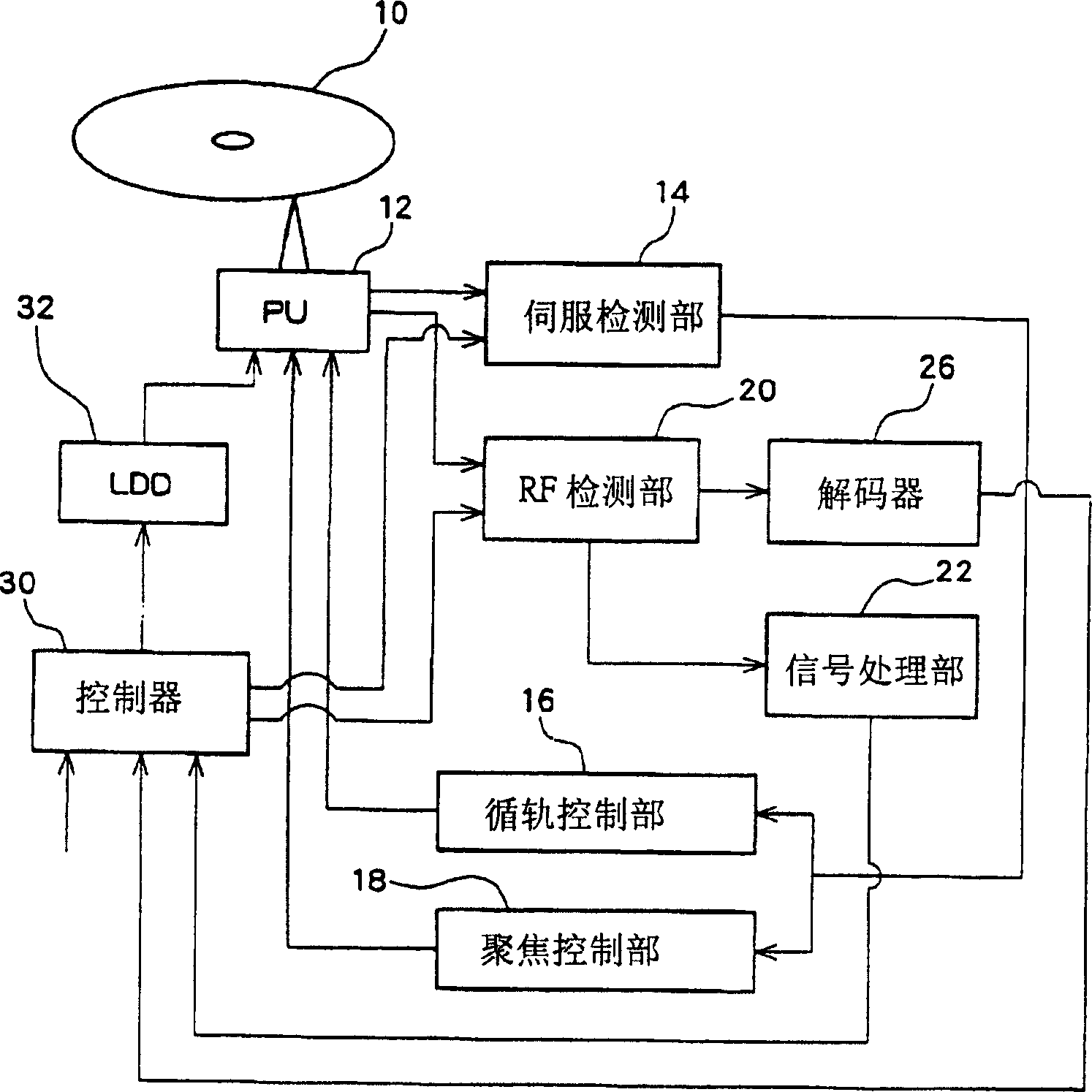
[0024] Hereinafter, embodiments of the present invention will be described by taking a DVD-R drive device as an example with reference to the drawings.

[0025] figure 1 It is a block diagram showing the configuration of the optical disc device of this embodiment. The optical pickup (PU) 12 faces the optical disc 10 (DVD-R), and has a structure including a laser diode (LD) and a photodetector that emit laser light onto the surface of the optical disc 10 . The laser diode is driven by a laser diode drive circuit 32 (LDD), and emits laser light at a reproducing power when reproducing data, and emits laser light at a recording power when recording. The photodetector of the optical pickup 12 is the same as the known structure using the differential push-pull method (Differential push-pull method), and is respectively provided with photodetectors for the main beam and the two sub-beams. 14 and the RF detection unit 20 output detection signals.

[0026] The servo detection unit ...


PUM


Abstract

An optical disk drive for optimizing laser power to be used at the time of recording operation. In a DVD-R drive and a DVD-RW drive, a controller performs OPC to set recording power and records RMD serving as recording management data in an RMA serving as a recording management area. The RMD are verified. When the RMD can be read, the number of PI errors in the RMD is detected. If the number of PI errors is equal to or less than an allowable value, data are recorded in a data area at that recording power. If the number of PI errors exceeds the allowable value, OPC is again performed, to thereby reset the recording power.

Description

technical field [0001] The present invention relates to an optical disc device, and more specifically, to a data-recordable optical disc device in which recording power is optimized. Background technique [0002] It is known that in drive devices such as CD-R / RW drives, DVD-R / RW drives, and Combos, there is a A technique for optimizing recording power. When recording data, test data is recorded in a test area (PCA area: power correction area) of an optical disc, and recording power is optimized based on the reproduced signal quality of the test data. This technology is generally called Optimum Power Control (OPC: Optimum Power Control), and data is recorded in the data area of ​​the optical disc with optimal power by utilizing the Optimum Power Control. [0003] Figure 6 An example of the flow of data recording processing in a DVD-RW drive is shown. First, DVD-RW is loaded on the drive device, and the controller in the device executes OPC (S101). Specifically, for exampl...

Claims


Application Information

Patent Timeline
Patent Type & Authority Applications(China)
IPC IPC(8): G11B7/0045G11B7/125G11B7/1267
CPCG11B7/1267G11B7/0045
Inventor 渡边光雄武田直人
Owner TEAC CORP
Why Eureka
Try Eureka