Resistance welding method, resistance welding equipment and method for manufacturing electronic component

A technology of resistance welding and electronic components, applied in the direction of resistance welding equipment, welding equipment, welding power supply, etc., can solve the problems of increased manufacturing cost, perforation of plate metal parts 12, and insufficient bonding strength, so as to reduce manufacturing cost and prevent processing The effect of defective products

Inactive Publication Date: 2004-08-04
MURATA MFG CO LTD
View PDF0 Cites 5 Cited by
  • Summary
  • Abstract
  • Description
  • Claims
  • Application Information

AI Technical Summary

Problems solved by technology

Therefore, only a small portion ( Figure 8 The part circled by middle ellipse 13) melts, resulting in insufficient bonding strength
[0006] And, since the concentrated current flows through a single part, excessive heat is generated at the part where the concentrated current flows, which sometimes causes a problem that the plate-like metal member 12 is perforated, and as a result the end 10a of the lead wire 10 is pierced. Through metal parts 12
In the case where the metal piece 12 is perforated or the lead wire 10 passes through the metal piece 12, the resulting bond strength is insufficient
[0007] In addition, since there is no equipment to check the bonding strength once welding is completed, sometimes defective products are sent to subsequent steps
In order to prevent this problem, an inspection step is required, which increases the manufacturing cost

Method used


Image

  • Resistance welding method, resistance welding equipment and method for manufacturing electronic component
  • Resistance welding method, resistance welding equipment and method for manufacturing electronic component
  • Resistance welding method, resistance welding equipment and method for manufacturing electronic component

Examples


Embodiment Construction

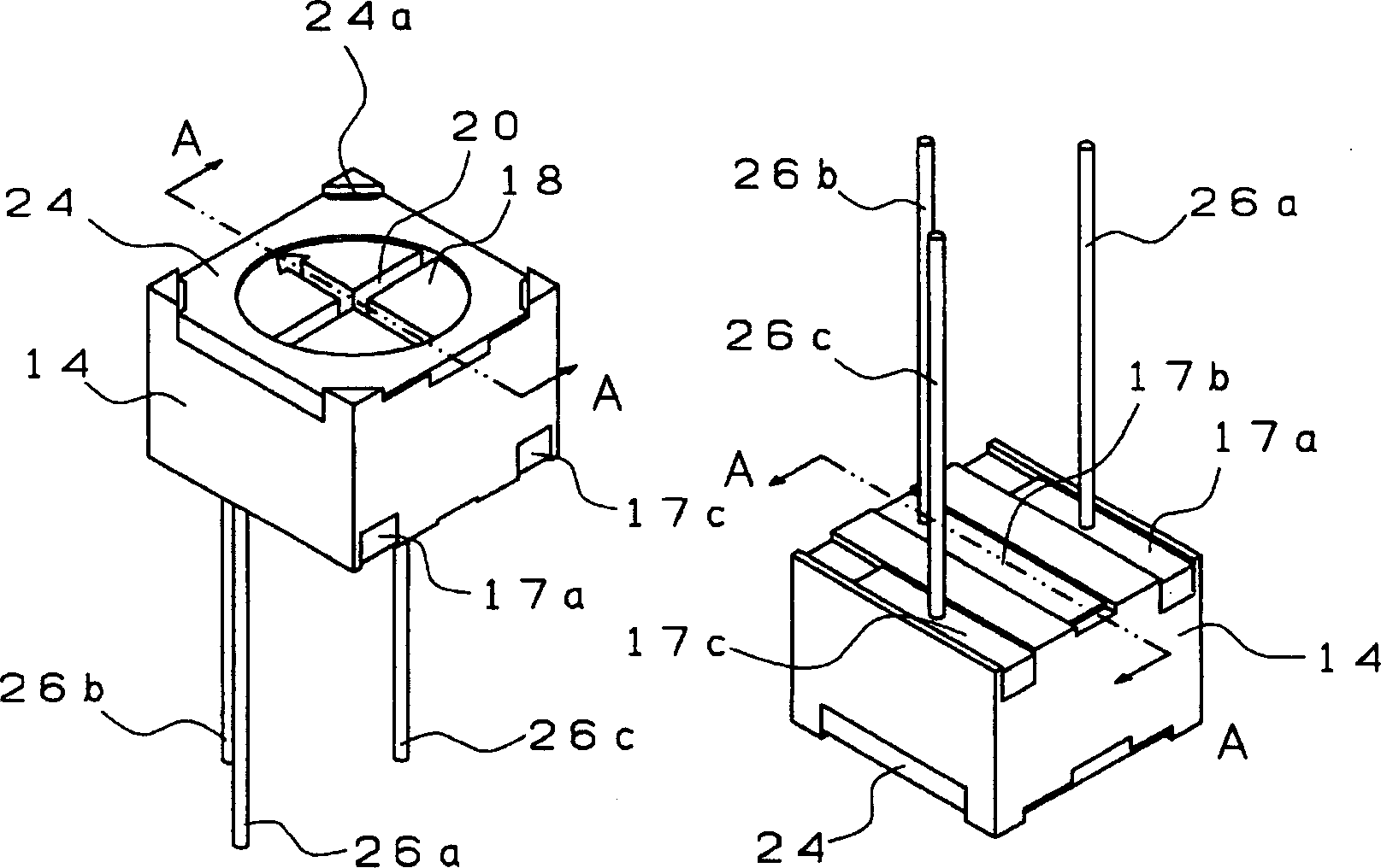
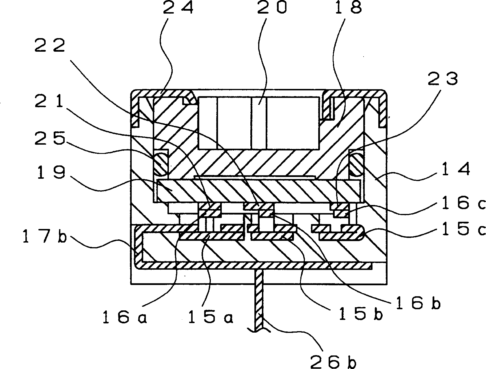
[0031] The structure of a variable resistor as an example of an electronic component used as a workpiece in a preferred embodiment of the present invention will be described with reference to FIGS. 1 and 2 . 1A and 1B are perspective views of variable resistors. figure 2 It is a sectional view of the variable resistor along line A-A in Fig. 1.

[0032] Such as figure 2 As shown, the variable resistor includes a housing 14, sliding contacts 15a, 15b, and 15c, a rotor, a metal cover 24, and lead terminals 26a, 26b, and 26c (wherein, the lead terminals 26a and 26c are shown in FIG. figure 2 not shown).

[0033] Housing 14 made of heat resistant resin or other suitable material includes recesses, sliding contacts 15a, 15b and 15c are bent upwards and their respective ends define arms 16a, 16b and 16c. Also, the sliding contacts 15a, 15b, and 15c are connected to external electrodes 17b, 17a, and 17c, respectively. Furthermore, the rotor is arranged in a recess in the housin...


PUM


Abstract

In a resistance welding method and a resistance welding apparatus which prevent a decrease in bonding strength between a lead wire and a metal member due to a partially formed current flow path and which immediately removes a defective component from a manufacturing line, a plurality of second welding electrodes in contact with the metal member is provided so as to provide a plurality of current flow paths, and accordingly, to prevent an unevenly distributed current flow. The bonding strength is measured to determine whether it is satisfactory or not on the basis of currents flowing through the second welding electrodes. Also, the electronic component is fixed by the second welding electrodes after resistance welded.

Description

technical field [0001] The present invention relates to a resistance welding method, a resistance welding device and a method of manufacturing an electronic component using the resistance welding method and device, in particular to a resistance welding method of at least one lead wire of an electronic component. Background technique [0002] Some electronic components, such as variable resistors, include leads provided therein for mounting on corresponding printed wiring boards. The leads are often bonded to the external electrodes by resistance welding. The general structure of the resistance welding equipment used for the aforementioned bonding is shown in Figure 7 middle. [0003] The resistance welding equipment includes a first welding electrode 1 holding a lead wire 10 , a second welding electrode 2 and a welding power source 3 . The lead wire 10 is in pressure contact with a plate-like metal member 12 provided on the upper surface of the electronic component body 1...

Claims


Application Information

Patent Timeline
Patent Type & Authority Applications(China)
IPC IPC(8): B23K11/00B23K11/25B23K31/12
CPCB23K11/006B23K2201/38B23K11/0053B23K11/257B23K31/125B23K2101/38
Inventor 大西克博
Owner MURATA MFG CO LTD
Why Eureka
Try Eureka