Heat-treating method for substrate and heat treating furnace

A heat treatment method and technology of heat treatment furnace, which are applied to furnaces, furnace components, furnace types, etc., can solve the problems of temperature distribution of substrates, inability to obtain uniform heat treatment quality, and difficulty in thermal influence, and achieve the effect of efficient transportation.

Inactive Publication Date: 2004-08-04
NGK INSULATORS LTD
View PDF0 Cites 12 Cited by
  • Summary
  • Abstract
  • Description
  • Claims
  • Application Information

AI Technical Summary

Problems solved by technology

[0007] Usually, partition walls or the like are provided between heating chambers to prevent the influence of heat from adjacent heating chambers, but it is difficult to completely prevent mutual thermal influence in adjacent heating chambers with different temperature settings.
Therefore, as described above, even if the temperature of the heating mechanism is consciously controlled to keep the temperature in each heating chamber constant, the temperature of the substrate that has been heat-treated for a predetermined period of time in the heating chamber will be affected by the heat from other adjacent heating chambers. There is a problem that uniform heat treatment quality cannot be obtained due to the difference in the transport direction due to the influence of
[0008] Moreover, even if any transport mechanism such as a roller conveyor, a chain conveyor, or a rocking beam is used to transport the object to be heat-treated to the adjacent heating chamber, it takes several tens of seconds to several minutes, so the temperature varies depending on the set temperature. When transporting substrates between adjacent heating chambers, the front part of the transport direction (the part of the substrate near the furnace exit side) that is first transported to the heating chamber of the moving destination is compared to the rear part (the part of the substrate close to the furnace entrance) that is transported later. part on one side) will eventually cause a difference in the heating process, and as a result, there will be a problem of temperature distribution in the substrate

Method used


Image

  • Heat-treating method for substrate and heat treating furnace
  • Heat-treating method for substrate and heat treating furnace
  • Heat-treating method for substrate and heat treating furnace

Examples


Embodiment Construction

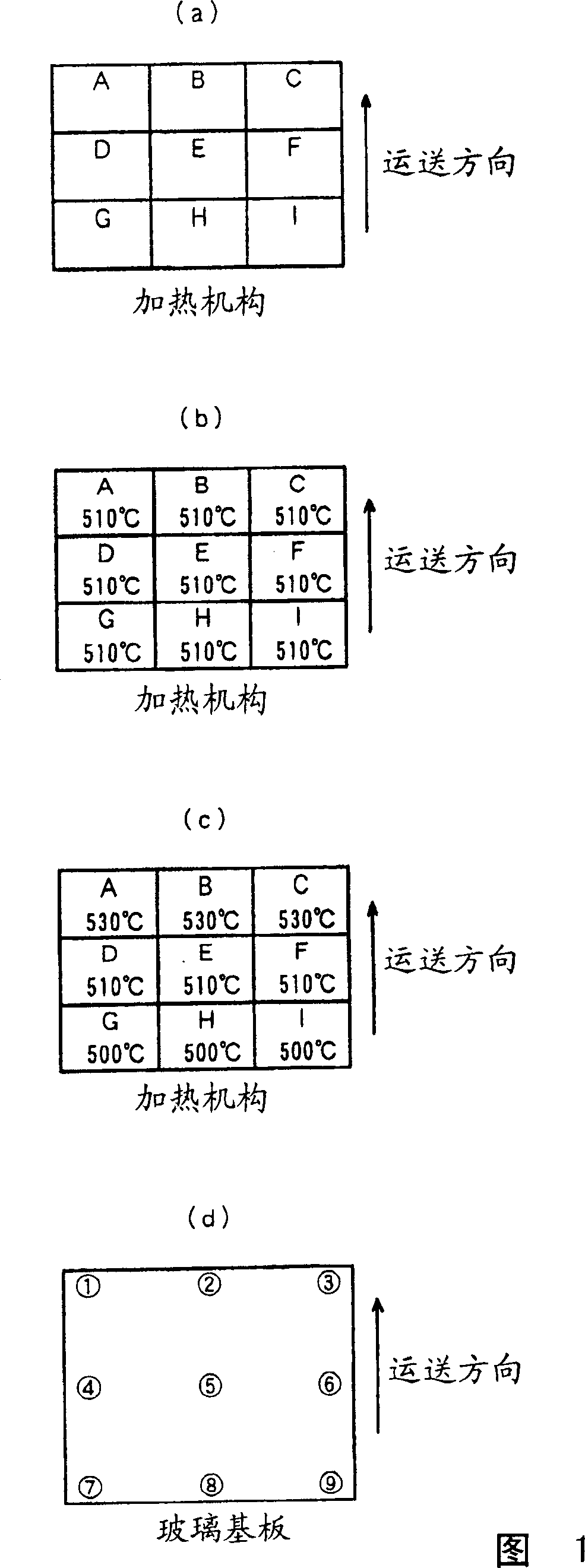
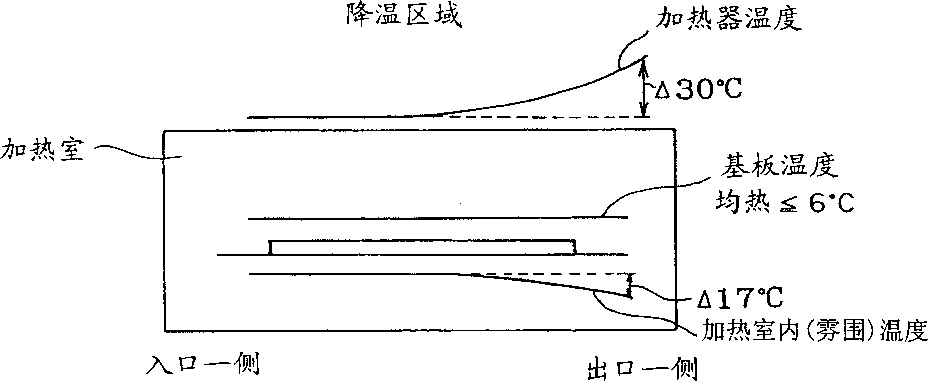
[0019] The heat treatment furnace used in the heat treatment method of the present invention includes a plurality of heating chambers divided in the conveying direction of the heat-treated object, and a conveying mechanism for conveying the heat-treated object to the adjacent heating chamber. Each heating chamber is provided with a heating mechanism that is divided into several at least in the conveyance direction of the object to be heat-processed. These divided heating mechanisms can be individually temperature controlled by independent control systems.

[0020] In addition, it is preferable that the above-mentioned conveying mechanism adopts a conveying mechanism of an intermittent feeding system that intermittently conveys the object to be heat-processed to the adjacent heating chamber. Here, "intermittently conveying" means repeatedly making the object to be heat-treated stationary in the n-th heating chamber from the entrance side of the furnace, and after performing hea...


PUM


Abstract

Provided is a method of heat-treating a substrate and a heat treatment furnace capable of uniformly heat treating the entire part of the substrate by suppressing the occurrence of temperature distribution in the substrate by thermal effect thereon from the other adjacent heating chamber with a different average indoor temperature from that in a heating chamber when heat-treating the substrate including a film formation material is performed in the heating chamber of a furnace. In the heating chamber with the different average indoor temperature from that in at least one chamber of the plurality of heating chambers (25, 26, 27) divided in the carrying direction of a heat-treated body, the set temperatures of electric heaters (14) for heating installed in the heating chambers are controlled so as to be different in the carrying direction of the heat treated body (22). In the heating chamber, temperatures at the inlet and outlet of the heat treated body (substrate) (22) in the carrying direction are maintained to have a distribution larger than a target temperature distribution in the substrate (22) so that the substrate (22) can be uniformly heat-treated.

Description

technical field [0001] The present invention relates to a heat treatment method of a substrate including a film-forming material represented by a glass substrate for a plasma display panel and a heat treatment furnace used therein. Background technique [0002] In recent years, the practical use of a large-screen flat panel display (hereinafter referred to as "FPD") utilized as a wall-mounted television or a display for multimedia has progressed. As such a large-screen FPD, the most competitive one is a plasma display panel (hereinafter referred to as "PDP"), which has a large viewing angle because of its self-illumination type, and has the advantages of good quality display and The manufacturing process is simple and easy to scale up. [0003] Manufacturing of PDP such as image 3 As shown, on the surface of large glass substrates called front glass and back glass, various components such as electrodes, inductors, and phosphors are successively formed by repeating the prin...

Claims


Application Information

Patent Timeline
Patent Type & Authority Applications(China)
IPC IPC(8): F27B9/02F27B9/08F27B9/40F27D19/00H01J9/24H01J9/48
CPCH01J9/48H01J9/242
Inventor 青木道郎
Owner NGK INSULATORS LTD
Why Eureka
Try Eureka